Make a question to Salas for the output voltage tha needs your motor.
In addition with two trimpots R7 and a switch you can have the 33 and 45rpm.
Yes a basic circuit with lm317 regulator is the power supply!
The 317 is a prereg. Basically you need to allow 5V for it and then another 5V at least for the next reg down to most DC motor requirement. The Mosfet across output will not allow under 4V to motor, in some situations less is needed, then you got to use an MJE350 with a 47R base stopper instead of the 220R. Will go lower then. 500R trimpot is for 5-6V range. 3.3k would drop for 16-20V for instance with adequate input voltage of course.
OK! Based on the input, here's version 3!
I also added the filter caps at the motor, in the event these have some impact on the other component values... (These were suggested by the motor manufacturer, and are available as an internal option for additional cost.) I will just stick them outside, although they said they are most effective as close to the brushes as possible.
I also added the filter caps at the motor, in the event these have some impact on the other component values... (These were suggested by the motor manufacturer, and are available as an internal option for additional cost.) I will just stick them outside, although they said they are most effective as close to the brushes as possible.
Attachments
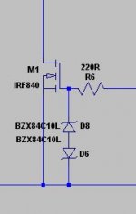
R9=27r would be OK, its just a base stopper, not particularly necessary in non problematic layouts with not enough nH to base though. Gate Zeners should be 2 back to back so to be complete, but never failed without yet.
If R9 is missing, the Vds for Q5 is clamped at 0.7V or so, and Q5 will never go into pinch off, and so never act as a constant current diode. With R9 missing, no need for Q5, it can just be a resistor instead.
OK! Based on the input, here's version 3!
I also added the filter caps at the motor, in the event these have some impact on the other component values... (These were suggested by the motor manufacturer, and are available as an internal option for additional cost.) I will just stick them outside, although they said they are most effective as close to the brushes as possible.
Zd2 should look down. Those motor caps may create reg oscillation. Try with and without.
Would both ZD1 and ZD2 look down? I can't see having two back-to back looking opposite ways doing more than cutting the wire would...
I just added the second one where the first one was (and the same polarity).
Easy enough to change.
Would you suggest running with no caps at the motor and see how 'smooth' it runs before I bother with the filter caps? It certainly simplifies things if I leave them off...
I just added the second one where the first one was (and the same polarity).
Easy enough to change.
Would you suggest running with no caps at the motor and see how 'smooth' it runs before I bother with the filter caps? It certainly simplifies things if I leave them off...
It has been working without a BC550 base stopper many times before. 0.7V across a 2SK170BL is more than double its -0.5V pinch off average.
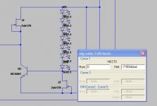
So what is this graph telling us?
Attachments
OK Guys.
here's version 4!
Are we happy with the values and placements/polarity (Red items are in quesation, but it should all be checked I guess)?
I am getting married Friday so I will be away from this for a week to two weeks. I would like to put together a BOM and order parts when I get back.
I also need to know what transformer (specs and type) I need to feed this regulator, and do I need a bridge rectifier too? Shall I make one, or just get a pre-made one? Do you think we need any additional capacitance after the bridge rectifiers, and before "V in" on this schematic?
Attachments
Make a bridge out of MUR120 diodes, and get a trafo capable to give rectified Vin about 12V more than V motor. Trimmers should be 5kOhm if you think your motor is going to run near 20V. 500R was for a motor that was running around 5V. For R8 use a 10k trimmer. R9=27 Ohm will do the job fine.
Sounds good. Here's the info on the required output:
To get my platen to spin at 45 RPM I need 18.947 volts (in theory- probably a touch more to overcome frictional losses)
And, for 33.333 RPM I need 14.035 volts (again in theory- probably a touch more to overcome frictional losses)
Based on that, I need ~31V input. So, should I be looking for a transformer with ~35V output to feed this?
I will also change the values you mentioned and create version 5 of the schematic tomorrow. I have to sleep now!
Sounds good. Here's the info on the required output:
To get my platen to spin at 45 RPM I need 18.947 volts (in theory- probably a touch more to overcome frictional losses)
And, for 33.333 RPM I need 14.035 volts (again in theory- probably a touch more to overcome frictional losses)
Based on that, I need ~31V input. So, should I be looking for a transformer with ~35V output to feed this?
I will also change the values you mentioned and create version 5 of the schematic tomorrow. I have to sleep now!
Transformer with ~28V output is ok, maybe the 25v is better (for example a 2x18v tranformer in papers, is around to <2x24v)
Last edited:
Are we happy with the values and placements/polarity
I don't agree with them. But Salas says we should ignore the behaviour of their devices as published by Toshiba. You can but try.
Not looking to start a war here!
I don't understand this very well, so I am relying on you guys.")
Like I said, it will be over a week before I am ready to order parts, so we have time to come to a concensus... Maybe shoot the middle between the values suggested by each? Not sure.
I don't understand this very well, so I am relying on you guys.
Like I said, it will be over a week before I am ready to order parts, so we have time to come to a concensus... Maybe shoot the middle between the values suggested by each? Not sure.
- Status
- This old topic is closed. If you want to reopen this topic, contact a moderator using the "Report Post" button.
- Home
- Amplifiers
- Power Supplies
- Turntable Motor Power supply