Pierre said:Thanks for the transistors suggestion.
I first thought on something more "usual" like 2n3904, but unfortunately their Vce rating is only 40V. I need something like 70-100V (Vcc modulator + (-Vrail max) + some margin)
My mistake you're right, I thought that 6.3 was referenced to the negative rail as well... sorry
")
BTW I like your decoupling.
Charles, about NFB:
The response looks quite good experimentally. With resistive loads, there is no trace of inestability at any point of the signal. Sound is very good for my taste also. The only hint observed is some HF oscillation at certain high amplitudes with my test loads (JBL TR225 2x15"+tweeter), perhaps they are too complex.
Is that normal/acceptable?
Salut Pierre
Do you have any possibility to use a dummy load that shows about the same impedance as the speaker box above the audible range ? This would be convenient for testing of loop stability.
Regarding the level shift transistors: They can be operated faster if used as common base - but this would make more changes to the circuit necessary.
The soft start solution I was talking of would also need quite some circuit effort in your case.
It could be implemented easier whith a topology that uses two comparators to achieve tuneable dead-time (i.e. window comparator) like Kanwar uses. One would just begin with infinite dead-time and gradually reduce it to the final value upon startup - this would mean the same as gradually changeing from a class-BD to a class-AD amp.
Regards
Charles
Very valuable suggestion, alfsch, Thanks!
From your experience, what is the typical situation for a typical box? all switches activated? (or all except one of the 8 ohm resistors for 8 ohm loads). I suppose that model doesn't include the typical crossover effects, right?
I will recalculate the simulations to see how phase margin is affected with these loads.
Best regards
With the dummy load model proposed, 8 ohm resistance, the simulations show that phase margin is reduced to around 25º.
That's quite small, so I decided to change the feedback cap from 33pF to 56pF, and that seems to improve things a lot and produce a phase margin of around 42º.
I have to test that change in the real amplifier, and then I will tell you...
That's quite small, so I decided to change the feedback cap from 33pF to 56pF, and that seems to improve things a lot and produce a phase margin of around 42º.
I have to test that change in the real amplifier, and then I will tell you...
imho typical box impedance is not useful.
more difficult for amps is cap. or ind. load, as i wrote;
cap is about like using a el.static speaker,
ind. like a bass-chassis only .
so you see r..real load (never real for real speakers
cap / ind or both : load with +/- phase for current.
if a amp has no problem with any combination, you can assume, it will be stable with most or maybe all speakers.
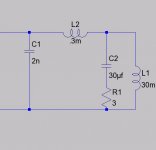
the ind. load i use is more complex :
it simulates a bass-speaker with typical resonance...
more difficult for amps is cap. or ind. load, as i wrote;
cap is about like using a el.static speaker,
ind. like a bass-chassis only .
so you see r..real load (never real for real speakers
cap / ind or both
: load with +/- phase for current.if a amp has no problem with any combination, you can assume, it will be stable with most or maybe all speakers.
the ind. load i use is more complex :
it simulates a bass-speaker with typical resonance...
Attachments
Kanwar. Your proposal is welcome.
Unfortunately, I won't be doing the tests until Monday, but the last one you have proposed really worths the pain, as it will tell me to what extent the effect is due to output stage + filter estabilization or if control (NFB or offset) is the culprit.
Best regards,
Pierre
Unfortunately, I won't be doing the tests until Monday, but the last one you have proposed really worths the pain, as it will tell me to what extent the effect is due to output stage + filter estabilization or if control (NFB or offset) is the culprit.
Best regards,
Pierre
Hi Pierre,
I once had problem with the IR2113 device when its
different supplies did not come up in the right sequence.
I think that the logic supply must come up first otherwise
it may show erratic operation during power up, regardless
the state on the SD pin.
Just an idea.
/ Mattias
I once had problem with the IR2113 device when its
different supplies did not come up in the right sequence.
I think that the logic supply must come up first otherwise
it may show erratic operation during power up, regardless
the state on the SD pin.
Just an idea.
/ Mattias
Hi Pierre,
You haven't told about your problem Status...[turn-on/off transients]
Is it solved or not, if yes what type of changes have you made in your design, it would be very good for all of us to see your nice updated schematic..... and it would be quite also helpfull for diyer's knowledge bank....
cheers,
K a n w a r
- Status
- This old topic is closed. If you want to reopen this topic, contact a moderator using the "Report Post" button.
- Home
- Amplifiers
- Class D
- Turn on/off transients