How do the power requirements change for a mono-block amp?
The mono-block choice means two separate power transformers filter chokes and chassis, one set for each amp. The pair of OPT's will be the same either way.
This will raise the cost and total weight somewhat, but make each amp chassis lighter if that is a major factor. It does however open up the available options for power transformers. Since the OPT's are the easiest, lets look there first.
Is your current design for a KT88 amp now predicated on the 3300 ohm opts or could 5000 ohm ones be used?
I already have the 3300 ohm OPT's so that's what I must use. I got them a few years ago when I was going to make a sweep tube amp. Sweep tubes have much higher peak current capabilities. The 3300 ohm OPT's will make the most power, but impose the most stress on the KT88's and would not be wise for an amp used for continuous high power output.
Testing early in the thread revealed that the 3300 ohm OPT's did good up to about 55 watts, 5000 ohms to 45 watts and 6600 ohms to 40 watts with a 450 volt supply. Power supply cost and risk goes up quickly over 450 volts.
They also make a 3400ohm 50-watt transformer.
Based on the numbers above I would suggest a 3300 -3400 ohm OPT if your B+ is below 440 volts, a 4000 - 4200 ohm OPT if the B+ is 425 to 450 volts, and a 5000 ohm OPT for B+ over 450 volts. The 6600 ohm OPT just barely makes 40 watts on 450 volts, but might be good for higher voltages, over 475 volts.
I’m put off by the 9.75 lbs. weight of the CXPP100-5K, and wonder if the 50-watt at 6.75 lbs. would be sufficient.
The "real" power rating of an OPT isn't a fixed number like 50 watts. The power capability of a transformer is limited on the low frequency end by its inductance (based on the amount of wire) and the magnetic capability of the core before saturation (based on the amount of iron). The 4 pound guitar amp OPT's that I have been using for testing were rated by the manufacturer for 80 watts at 82 Hz (the lowest note on a standard guitar). I have had no problems extracting 175 watts from these transformers at 1000 Hz, but they would be hard pressed to pass 20 watts at 20 Hz.
I have never used a pair of the 50 watt Edcors. I have tested the 100 watt units and they will do 50 watts down to 16 Hz. They will do 75 watts down to 27Hz. I haven't tested them at 100 watts yet. So even the 100 watt Edcors won't do 100 watts at 20 Hz without some help (feedback). The 50 watt versions will probably do 35 watts down into the 25 to 30 Hz range, so they may be OK for your application.
I did some searching through the Edcor catalog to find that their 50 watt and 60 watt OPT's have the same weight, 6.75 pounds. I suspect that they are the same transformers, but don't know for sure. The 50 watt versions only come with a single impedance choice, and some are limited to 8 ohms....no 4 ohm choice. The 60 watt transformers have a 0-4-8-16 option and a fixed impedance option.
Power transformers:
I made the measurements in the YouTube video on a stereo amp making 70 WPC on 485 volts. It needed 400 to 450 mA average over 4 minutes when operated at the edge of clipping. Full power sine wave output takes 600 mA.
DC currents in this range preclude the use of any single rectifier tube. A pair of 5AR4's is marginal. The peak currents will over stress the 5AR4's. Amps like this usually run TV damper tubes (at least 4), mercury vapor tubes, or solid state diodes.
Power transformers that can deliver 485 VDC after rectification and filtering at 450 mA of current AND 9 amps of heater current are large, expensive and not common. I usually split this up between two smaller transformers which could weigh more, but cost less......shipping may eat some of the cost savings.
The 125 WPC versions of Pete Millett's Engineers Amp that I built used a surplus guitar amp power transformer for the heaters, negative bias supply, and 300 volt B+. An additional Antek power toroid was hidden under the deck for another 300 volt supply which was wired in series with the main 300 volt B+ to create 600 volts for the plates of the output tubes. All rectification was solid state. This technique can be used to create the power supply for a stereo version of this amp. I will be exploring ways to power a high powered (50+ watts) stereo amp in the near future.
Scaling the power back to 35-45 WPC makes a stereo amp with a single power transformer and rectifier tube possible. Dynaco made lots of ST70's with a single transformer and 5AR4. The ST70 power transformer made 720 volts CT at 300 mA. The ST70 ran the output tubes in pentode mode which makes a bit more power and is more efficient.
Am I correct in thinking that a 5V tap is not needed in this design?
The 5 volt winding would only be needed if you wanted to use a tube rectifier.
I am thinking that the Edcor XPWR 222 or the XPWR 214 might be the closest match:
I have not yet been able to find a single off the shelf transformer that will power this amp. At least a second small isolation transformer will be needed for the +/- 150 volt supplies.
Neither of the Edcor units you mention provide the 8.8 amps of heater power needed for 4 X 600 mA (6CG7) and 4 X 1.6 amps (KT88). This is the issue with many off the shelf transformers. A secondary heater transformer for the driver board (6.3 volts @ 2.4 amps) would be needed.
This one has the B+ and heater requirements met, and has enough power for two rectifier tubes, but it cost more than an Edcor. They have some decent OPT's too, but I have not tried any of their stuff in recent years.
PA060 S Dynaco ST70 Upgrade Power Transformer Replacement MADE IN USA
I'm guessing there is a suitable small transformer that covers both the extra heater power (6.3V @ 2.4 A) and the +/- 150 volt power (180 to 240 V CT @ 75 mA), but I haven't really looked for it yet. I will keep looking for the best solution. The XPWR039 will work, but it is serious overkill, and not cheap.
Mono blocks at 35 to 50 watts each make the power supply design much easier. About 15 years ago, I built at least a dozen guitar amps that used cheap Chinese KT88's and a single Allied Electronics 6K7VG power transformer....the same transformer I use in my SSE amps. The amps with rectifier tubes made 35 to 40 watts, the solid state versions made about 50 watts. Technically the main B+ current rating is a bit low, but if a dozen guitar players couldn't blow a transformer, they will live in a HiFi amp. The 90's vintage Chinese KT88's were another matter. Some of them only lived for a few weeks. I switched to Sovtek 6550WA's and they lived forever. I still have one quad, and they have been in my test amp.
There are several similar power transformers with the capabilities to run a 35 to 50 watt mono block. The Hammond 274BX or 374 BX, and Edcor XPWR010 come to mind. Any of these will still require a small isolation transformer like the Triad N-68X (ugly, but small enough to hide) and a suitable choke (cheap and ugly, or nice enough to put up on top of the deck), either way look for at least 4 Hy at 175 mA and a low DCR.
This setup provides about 425 to 450 volts with a 5AR4 tube rectifier, and 450 to 475 volts with solid state diodes depending on line voltage and transformer choice.
Last edited:
using two transformers to make the B+ makes good sense. I have 4 of these AS-2T230 - 200VA 230V Transformer - AnTek Products Corp. 2 for each mono amp. Parts are on hand for ss rectifies and crclc filter. I figure to rectify and Crc filter the two transformers separately and then combine the voltages for the last lc filter. I also thought I could tap one of the transformers to generate the screen supply. I’ll need to drop some voltage maybe another filter section with a high resistance or I do have regulators I could use.
For the MOSFET supply I have a couple of smaller toroidal transformers that have taps for the driver board heaters.
AS-05T120 - 50VA 120V Transformer - AnTek Products Corp
For the MOSFET supply I have a couple of smaller toroidal transformers that have taps for the driver board heaters.
AS-05T120 - 50VA 120V Transformer - AnTek Products Corp
rectify and Crc filter the two transformers separately and then combine the voltages for the last lc filter.
I built the 125 WPC version of Pete Millett's Engineers Amps this way. Each 2T230 will make a bit over 300 volts when rectified and filtered. I didn't use CRC, I just uses one big C 470 uF 400 Volt from a server power supply. I then wired two of these 300+ volt supplies in series for about 650 volts unloaded, about 615 with 4 output tubes biased to 30 mA each, and about 585 volts at full tilt, which was about 110 watts per channel. This fed the red wires on the OPT's without any additional filtering. I connected the bottom 300 volt supply to the board's B+ input. 300 volts feeds the driver tube's B+ and an on board mosfet regulator makes the 150 volt screen supply for the drivers and output tubes.
After the first amp was made we found some surplus power transformers on Ebay for $15. Tyeh had a bit better regulation than the Antek, so the bottom transformer was replaced with the surplus unit, and the top transformer remained an Antek. Plate supply voltage was now 605 volts at full crank and power output rose to 125 WPC.
for the MOSFET supply I have a couple of smaller toroidal transformers that have taps for the driver board heaters.
The 2T230's used for B+ also have 8 amps of heater power each. A pair per mono amp is plenty of heater power.
These will not work for the mosfet supply. To get +/-150 volts, you need two windings. A simple half wave rectifier with one end of the single winding grounded will indeed make +/- 150 volts, but the currents drawn must be equal or the transformer will not be happy. This is especially true with a toroid. The negative supply has about 20 mA extra drawn from it. You could try to balance the load with resistors, but I have not had good luck with that.
I use an isolation transformer with two 120 volt windings in series to make a 240 volt CT winding. The CT is grounded and a bridge and two caps connected in a manner similar to most solid state amps. I use the Triad N-68X because they are about $15.
Thanks for the direction on the triad transformer. I don’t know what I was thinking. I have built quite a few +\- solid state supplies.
I made some progress collecting parts and soldering on the driver boards. I am thinking about the resistors that are optional based on voltage/tube choice. It looks like I’ll be feeding the Mosfets +\- 150Vdc and the B+ to the driver board will be around 300volts. Any advice would be great. I don’t mind testing measuring and changing resistors but I don’t want to unsolder more parts then necessary
Thanks
Evan
Attachments
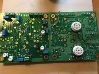
Here is the latest BOM. It is the one I used to populate the 4 boards that I have. I have changed R17 and R18 to 27K 3W in the boards on the test bench due to operation at 500+ volts. They are probably the only parts that will see more changes for a KT88 amp. Applying plate to plate feedback resistors from the output tube plates raises the plate voltage on the 6CG7's especially with high plate voltage on the output tubes. This makes some iterative tuning necessary when adding feedback to keep the 6CG7's happy.
I have included the BOM in PDF and in Excel format. The forum does not support .XLS files, so I changed the extension to .txt Change it to .XLS and it should open in any version of Excel since 2003. I still use old office software.
I have included the BOM in PDF and in Excel format. The forum does not support .XLS files, so I changed the extension to .txt Change it to .XLS and it should open in any version of Excel since 2003. I still use old office software.
Attachments
I made the measurements in the YouTube video on a stereo amp making 70 WPC on 485 volts.
Hey George,
Is the YouTube video mentioned above (#141) in this thread? I can't seem to find it.
Thanks,
Warren
Hey George,
Is the YouTube video mentioned above (#141) in this thread? I can't seem to find it.
Thanks,
Warren
See post #44
I picked up that same organ a few years back from a thrift store, for about the same price.
The tone wheel was seized on mine and
I had to recap and fix (tie together) a lube string, but it still sings today! I can't play the damn thing, but I've entertained the thought of learning")
The tone wheel was seized on mine and
I had to recap and fix (tie together) a lube string, but it still sings today! I can't play the damn thing, but I've entertained the thought of learning
Hi George,
I’ve been trying to decide whether to build a single amp or mono-blocks.
Here’s my understanding of what the minimum requirements for the power transformers are for each:
Mono-blocks:
4.4 amps at 6.3 volts
150ma at 720-750 volts
3 amps at 5 volts
A stereo amplifier:
8,8 amps at 6.3 volts
300ma at 720-750 volts
3 amps at 5 volts
Here are possibilities for mono-blocks:
Allied 6K7VG 150ma 750V 6.3V@5amps 5V@3amps
Hammond 274BX 201ma 720V 6.3V@6amps 5V@3amps
Hammond 374BX 201ma 720V 6.3V@6amps 5V@3amps
Edcor XPWR010 175ma 750V 6.3V@amps 5V@3amps
For a stereo amp the choices appear more limited:
Triode PA060 300ma 720V 6.3V@5amps 6.3V@5amps 5V@5amps
Toroid 236-5072 750ma 720 6.3V@5amps 6.3V@5amps 5V@6amps
Edcor XPWR222 350ma 750 6.3V@6amps 5V@6amps
Edcor LVP6.3-5 6.3V@5amps
Could the Edcor LVP6.3-5 be used with the XPWR222 to create enough 6.3 volt power?
Are the above assumptions correct?
Based on what you’ve written I’m thinking that I’ll go with 100 watt 3.3K Edcor output transformers.
Is there a schematic for the power supply that you can share?
Thanks, Jacques
Could the Edcor LVP6.3-5 be used with the XPWR222 to create enough 6.3 volt power?
You can't physically connect the outputs of two dissimilar transformers together since one will have a slightly higher voltage than the other, and will supply most of the current. You can however run one complete channel from the heater winding on the main power transformer, and the other channel's heaters from the small transformer.
Are the above assumptions correct?
The only one of your listed transformers that I have actually used in this amp is the expensive toroid. I have built guitar amps and KT88 based SSE's with the
Allied, and both Hammonds. All work fine. Spec wise the other choices look good.
Is there a schematic for the power supply that you can share?
I will see if I can make a drawing of what I had built and get it posted in the next day or two.
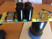
Got a bit of work done on a power supply board. CRCLC. I will feed it with two 230 volt transformers. I plan to have the large capacitor stick through the top with the rest of the components inside the chassis.
I am wondering hom much heatsink the ss rectifier bridges will need.
I am wondering hom much heatsink the ss rectifier bridges will need.
Attachments
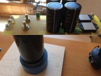
B+ should be around 600vdc. I’m using terminal blocks for the resistors in the crc filter so I can fine tune the voltage once the circuit is running.
My thinking is that by using a supply that produces +\- 300vdc I can get 600 volts for b+ as well as 300 volts for the screen supply. I’m still not sure about how to manipulate the screen voltage. Simple resistor to drop voltage or a full blown regulator.
My thinking is that by using a supply that produces +\- 300vdc I can get 600 volts for b+ as well as 300 volts for the screen supply. I’m still not sure about how to manipulate the screen voltage. Simple resistor to drop voltage or a full blown regulator.
Have you had the time to finish your amp?
Unfortunately I have had little time to work on it. I need a day of good weather to drag the big drill press out on the driveway and drill the base plate. The little one doesn't have the depth. The storm we just got.....is coming your way. The weather this winter has been whacked, to say the least!
I'm still trying to get a 1095-A form from the health care marketplace so I can file my taxes. I have been at this for nearly two months. Their escalation process "takes UP TO 30 days." We are now on day 41. Sherri or I call every day and get a different idiot with a different story every time. That story took over two hours, one "script reader" and two "supervisors."
My daughter pulled a bonehead move that has cost us about $1K so far, and taken several days to unwind, and we are still not done. The bank has done some questionable and possibly illegal moves as well.
Hopefully I can get back to it reasonably soon. I am putting the breadboard back together since the finished amp may not happen as soon as I thought.
I have some of the transformers listed in your monoblock choice, so I will set up a single channel as a mono block and document that. The channel that got blown up when the resistor arced is still dead, and I may need to build a new board, or steal one from the final amp project.
I’m still not sure about how to manipulate the screen voltage. Simple resistor to drop voltage or a full blown regulator.
A pentode amp wants "regulated" screen and bias bias bias supplies. The plate supply can be unregulated. The simple resistor for the screen usually does not provide the lowest distortion, however a full blown feedback regulated screen supply is overkill. A mosfet follower with it's gate tied to a zener or gas tube regulator stack is fine, and what I use. Others use the "Maida" regulator made with an LM317 or similar low voltage part and a mosfet. It may provide better performance.
Sorry to hear about your hardships and yes the weather has been crazy. We have what looks to be well over a foot on the ground and it’s still coming down. I have deadlines at work and need to get to the shop or I’ll have to work all weekend so I’m off to shovel.
I got the main supply board put together and will start on the screen supply and +/- mosfet supply this weekend. Thanks for the guidance.
Evan
I got the main supply board put together and will start on the screen supply and +/- mosfet supply this weekend. Thanks for the guidance.
Evan
Just file an extension - no more pressure.......isn't a big deal and obviously wouldn't apply if you're getting a refund.
An extension has already been filed. We should be getting a sizeable refund since we will be claiming at least $22K in medical expenses which is almost half our income for 2017. We have found that neither the insurance company or the marketplace will do anything unless we are on their a$$, and each blames the other. 3 way phone calls with both parties end in nastiness, or one party hanging up......it just sucks!
Incompetence, deception and possible fraud at the insurance company has left us with some large medical bills floating on credit cards costing us money in interest, which the refund will pay off.
Example....I had a minor cancer surgically removed in a hospital in March of last year. After arguing about the bill for almost a year, they covered $47 of a $1600 bill, and billed us for the remainder in 2018, too late to be claimed on our 2017 taxes. We have three such cases totaling about $2.5K, all bills came in 2018. We could have claimed them on 2017 taxes if the ins co had done their job.
My daughter, her husband and 4 kids have been freeloading in a house we own and could sell. This has put us in a negative cash flow situation for the last 3 years and caused considerable friction in the family.
Tubelab Inc. hasn't made money in several years and my wife is not happy about the time VS payoff situation. She has taken a part time job to make a few bucks, which leaves me doing the housework and dealing with the daughter's family disasters.
There aren't many employment opportunities for a 65 year old retired cell phone designer, especially here.
Sorry about the rant, but I will try to get back to Tubelab in the next few days.
- Home
- More Vendors...
- Tubelab
- Tubelab Universal Driver Board, 2015 version