After reading this thread : http://www.diyaudio.com/forums/showthread.php?s=&threadid=129396 I hoping someone could give me some advice on a power transformer I have aquired for use with tubelab Simple SE. I have a power transformer with the following spec 375-0-375 @ 175mA with centre taps at 50V @ 50mA, 6.3V CT @ 6A and 5V CT @ 3A.
to connect to the he 5 volt rectifier filament and the 6.3 volt filament wire to the board should I just connect the wires that are labelled 3.15 to each of the 6.3 volt filament connections and 2.5v to each of the 5 volt rectifier filament connectors? Sorry if this is a dumb question help is appreciated!
to connect to the he 5 volt rectifier filament and the 6.3 volt filament wire to the board should I just connect the wires that are labelled 3.15 to each of the 6.3 volt filament connections and 2.5v to each of the 5 volt rectifier filament connectors? Sorry if this is a dumb question help is appreciated!
It should look something like this:
The green pair on the left edge is the 6.3V. The yellow pair on the top edge is the 5V. The red pair is either end of the high voltage (375 - 375) winding. The red with the stripe is the center tap of the high voltage winding. Note that it goes to a different Phoenix block than the solid red wires.
Do not connect the center tap of the 6.3V (green striped) to anything. Do not connect the center tap of the 5V (yellow striped) to anything. Do not connect the 50V tap (purple) to anything. If you have these wires, carefully wire nut or tape them back where they cannot touch anything.
George has some pretty good wiring diagrams here:
http://tubelab.com/SimpleSE_wiring.htm
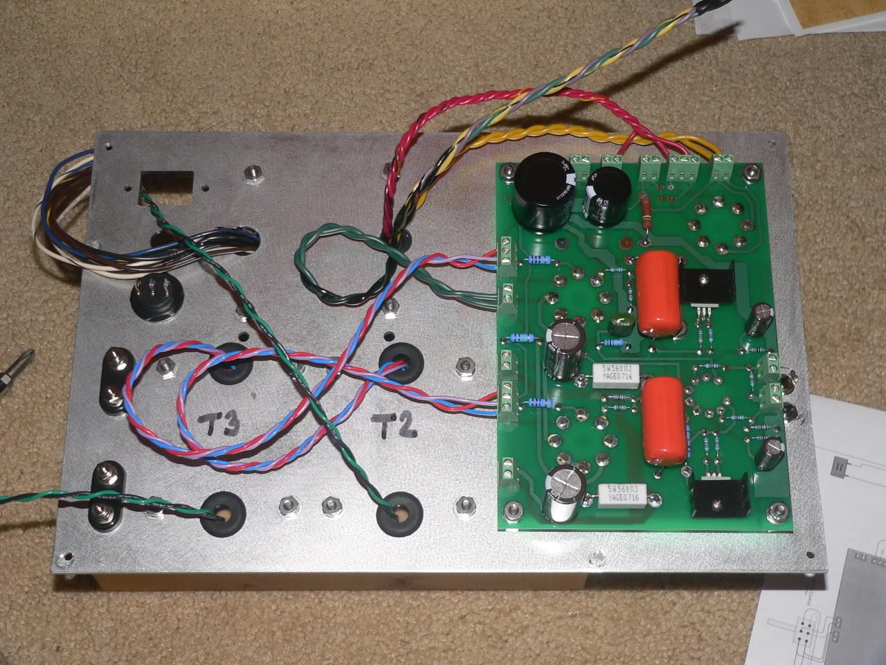
to connect to the he 5 volt rectifier filament and the 6.3 volt filament wire to the board should I just connect the wires that are labelled 3.15 to each of the 6.3 volt filament connections and 2.5v to each of the 5 volt rectifier filament connectors? Sorry if this is a dumb question help is appreciated!
Good question, and TY is correct.
Connect each 3.15 volt wire to a 6.3 volt terminal (labeled T1-GRN). These wires are usually green. Do not connect the 0 volt wire associated with these 3.15 volt wires (usually green with a black stripe) to anything.
Connect each 2.5 volt wire to a 5 volt terminal (labeled T1-YEL). These wires are usually yellow. Do not connect the 0 volt wire associated with these 2.5 volt wires (usually yellow with a black stripe) to anything. This wire operates at a high DC voltage, make sure that it is well insulated.
Each 375 volt wire goes to a high voltage terminal (labeled T1-red). These wires are usually red. The center tap (usually red with a yellow or black stripe) goes to either T1-RED-YEL terminal. The 50 volt tap is not used in this design.
Look at the following transformer schematic (courtesy of Hammond):
http://www.hammondmfg.com/263sch.gif
The Red/Yel, Yel/Blk and Grn/Yel are center taps for their respective windings. you would equal voltage from the center tap to either winding end but 180 degrees out of phase.
Regards, KM
http://www.hammondmfg.com/263sch.gif
The Red/Yel, Yel/Blk and Grn/Yel are center taps for their respective windings. you would equal voltage from the center tap to either winding end but 180 degrees out of phase.
Regards, KM
In the same way
Two questions
For the Power transformer, I have the Hammond 374BX.
If I want to use it at 120V, will I use the BLK and WHT cable only?
I won't use the BLU and the BRN?
For my OPT, I have the Tango U-808.
How do I connect it to the T2-PRI and to T3-PRI?
The schematic is for the Tango.
Two questions
For the Power transformer, I have the Hammond 374BX.
If I want to use it at 120V, will I use the BLK and WHT cable only?
I won't use the BLU and the BRN?
For my OPT, I have the Tango U-808.
How do I connect it to the T2-PRI and to T3-PRI?
The schematic is for the Tango.
Attachments
For your 374BX you must use both primaries in parallel. You should connect the white wire to the brown wire this is one side of the 120 volt supply. The black and blue wires are connected together for the other side of the 120 volt supply. This is shown on the hammond web site. Look at the 120 volt wiring diagram near the bottom of the page.
http://www.hammondmfg.com/300series.htm
Connect the B terminal on your Tango to the T3-PRI terminal closest to the large power supply cap. The SG treminal goes to the center connection on the connector and the P terminal goes to the terminal on the right as viewed from the top with the board oriented so that the writing is correct.
tigrine said:After I had follow your information.
I just put my 5AR4 only and check the B+.
My B+ is 555 Volts. I check the red cable T1-RED(375-375).
My multimeter indicate 808 volts.
What's wrong ?
Nothing is wrong. With no power tubes in the circuit, the B+ will be much higher (unloaded voltage). Install the output tubes, and B+ will settle down to around 450 volts.
Don't run it for long with no output tubes installed. I'm not sure your power supply capacitors are rated for >500 volts.
tubelab.com said:For your 374BX you must use both primaries in parallel. You should connect the white wire to the brown wire this is one side of the 120 volt supply. The black and blue wires are connected together for the other side of the 120 volt supply.
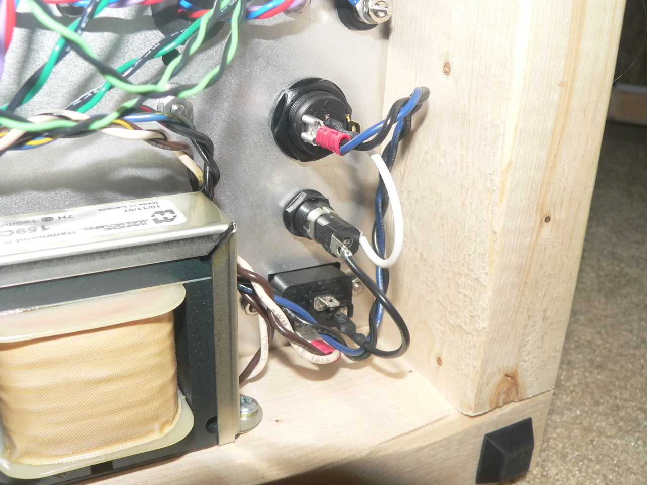
It will look something like this when you are done. The hot lead on the power connector jack goes to the fuse first, and then to the power switch. The other side of the power switch goes to both the black and blue leads of the 374BX. The white and brown leads of the 374BX both go to the neutral lead of the power connector.
Of course, if you live where the line voltage is 240V then the wiring is different.
After I checked all the connection, I saw that every cable were in place.
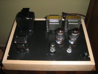
But, when I turned it on, I had no sound. Finally, the problem come from the pot (100k). I changed it and the SimpleSE began to sing!
Thanks George for your help and generosity.
But, when I turned it on, I had no sound. Finally, the problem come from the pot (100k). I changed it and the SimpleSE began to sing!
Thanks George for your help and generosity.
Attachments
- Status
- This old topic is closed. If you want to reopen this topic, contact a moderator using the "Report Post" button.
- Home
- More Vendors...
- Tubelab
- tubelab SimpleSe power transformer connection question