oldmanStrat said:I bought mine from AES - just the cheapo chinese 6L6GC's. I have no idea if spending more would produce better sound
One interesting thing with these tubes - the plate is glowing red in spots. I double checked the table George has on the cathode resistor (mine is 560) and it should be right in the middle of the possible selections. I don't think there is an issue, but perhaps a better quality 6L6GC wouldn't do this...
Glowing in spots is generally not a good thing and usually means some misalignment of the cage and/or unevenly coated cathodes. If what you see are vertical lines on the plate, then this is normal for some beam tetrodes because the electron cloud is formed into a flat beam that strikes the plate. Many big beam tubes are setup so that the beam hits right where the plate halves join. The seam forms a wing that helps dissipate the heat. Other tubes, like the Philips 6V6GTs in my Thomas amp, have the beam hitting the flat center part of the plate. On some of these, it is supposedly OK for a dull red line to appear. If you know the voltage and current and are well within the plate dissipation of the tube, you should be OK.
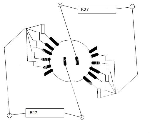
Sorry guys for bringing this back up, but I just don't get it. Cathode Bias? Thats R17 and R27. I'm using the 560ohm 5w in both. You can see my Transformer etc. in my signature.
I've been using JJ E34L's for about 10 hours listening. It's the first time I've paid any attention to the glow of a tube, so I have nothing to compare it to. Likely, from what I've been reading here, I should raise the ohm value of (both R17 and R27?) 560ohm. I want to install a cathode bias select like Russ describes below.
Quote from Russ about varying the bias:
"The cathode bias select is simple. I have a spreadsheet that you can use to build a list of resistor values, if you want. The switch just selects a resistor to put in parallel with a 680 ohm that is always there. The actual values are something like: 564, 468, 434, 389, 357, and 340 ohms. Since there is always a 680 ohm resistor there, even when the switch is between contacts, I can turn the switch while the amp is on. The bypass cap slugs-out the switching enough that I don't hear any popping or anything. In fact, it takes some time for the new bias voltage to settle-in. Kinda fun to "hear" the various settings for different tubes."
First off, how do I use a meter to find my B+?
So I have to know my B+ first to know how to proceed with installing the switch? Say I leave the 560ohm resistors in place, solder a wire to one end of these resistors(R17 and R27). Which end? To more resistors soldered to a switch? Whats the bypass cap? The picture of the switch makes that end of the installation fairly understandable to me. I'd love that spreadsheet of resistor values please. It's not likely that I will use any more than el34's, kt88's or 6l6's. in the near future.
I saved 4 Canadian Marconi Co. 25CH SSB Transceivers from going to the landfill and their full of resisters, switches and other parts I can use.
The most accurate way to get the plate voltage is to measure it at the plate. On the SSE, this can be done at the transformer connection. This is typically the blue wire of the OPT.
As to the cathode resistors, the bypass cap is already on the PCB. All you are doing is putting more resistors in parallel to the one on the board. That reduces the total resistance. A lower resistance means a lower grid-to-cathode voltage...less bias. That makes the tube conduct more. You actually get some feed back here because the increased tube current through the resistor increases the grid-to-cathode voltage again somewhat. This is why cathode bias is often called "auto bias". The mechanism can adapt to different tubes and tube wear (to some degree). The only way to move the operating point in cathode bias is to change the resistance itself. The resistance is calculated by:
1/R1 + 1/R2 = 1/Rtotal
In the attached is a bit overcomplicated, as I was going back and forth between the resistance I wanted and the actual values that are available. To summarize the columns:
Ik = expected cathode current in mA (also plate current when in triode) from George's table.
Rk= target resistance
Rk actual = total final resistance calculated from R1 and "R2 avail"
Vk = expected grid-to-cathode voltage
Pk = total expected power dissipation through the resistor
R1 = this is the one on the PCB in my case
P1 = power dissipated by R1
R2 = required R2 value to hit Rk
P2 = power dissipated by R2
R2 avail = actual resistance value available
P2 actual = actual power dissipated by R2
Attachments
To find your B+ you need to measure between ground and the blue wire from the opts on tubelabs diagram.HEADinaJAR said:Sorry guys for bringing this back up, but I just don't get it. Cathode Bias? Thats R17 and R27. I'm using the 560ohm 5w in both. You can see my Transformer etc. in my signature.
I've been using JJ E34L's for about 10 hours listening. It's the first time I've paid any attention to the glow of a tube, so I have nothing to compare it to. Likely, from what I've been reading here, I should raise the ohm value of (both R17 and R27?) 560ohm. I want to install a cathode bias select like Russ describes below.
Quote from Russ about varying the bias:
"The cathode bias select is simple. I have a spreadsheet that you can use to build a list of resistor values, if you want. The switch just selects a resistor to put in parallel with a 680 ohm that is always there. The actual values are something like: 564, 468, 434, 389, 357, and 340 ohms. Since there is always a 680 ohm resistor there, even when the switch is between contacts, I can turn the switch while the amp is on. The bypass cap slugs-out the switching enough that I don't hear any popping or anything. In fact, it takes some time for the new bias voltage to settle-in. Kinda fun to "hear" the various settings for different tubes."
First off, how do I use a meter to find my B+?
So I have to know my B+ first to know how to proceed with installing the switch? Say I leave the 560ohm resistors in place, solder a wire to one end of these resistors(R17 and R27). Which end? To more resistors soldered to a switch? Whats the bypass cap? The picture of the switch makes that end of the installation fairly understandable to me. I'd love that spreadsheet of resistor values please. It's not likely that I will use any more than el34's, kt88's or 6l6's. in the near future.
I saved 4 Canadian Marconi Co. 25CH SSB Transceivers from going to the landfill and their full of resisters, switches and other parts I can use.
I built a cathode bias switch also. I used a DPDT switch on-off-on. In the up position I get 660ohms, middle position 820, and lower position 560ohm. I am going to redo these because I thought my B+ would have been a bit higher. I just have my resistors in parallel with an 820ohm resistor on the board that when flipped a resistor is paralleled with it to lower the value. I really like the switch Russ has. You may want to either add a larger resistor or else wire one up in series with your 560ohm to raise the value so you have something to parallel with. Here is a site I used for calculating valuesLINK TO SITE
Russ do you have a part number for that rotary switch you used?
Nice pic, Paul. Yep, that's the gist of it. If you look closely at the pic of my switch, you may notice that there is no unused pole on the switch and there seems to be an extra pair of wires going off somewhere. The extra pair leads to the 620 ohm resistors which are 5W and mounted to the chassis. I don't actually have a setting that only uses the on-board 680 ohm. My intent was to figure out which setting I didn't use or used the least and cut that one out.
One thing I have noticed with my simple SE is that my 6l6gcs show some red glowing on the plates when the bias switch is in the 660ohm position. It is concentrated in one area on each tube. It almost looks to be inline with the filament. I have tested my B+ and I get an even 450volts. I may have to try a different resistance and see if it is still an issue. It could also be that they are the cheap chinese coke bottle tubes.
Sometimes it's OK. I mention it above in this post:
http://www.diyaudio.com/forums/showthread.php?postid=1835050#post1835050
http://www.diyaudio.com/forums/showthread.php?postid=1835050#post1835050
rknize said:Sometimes it's OK. I mention it above in this post:
I dunno about that. If the plates are hot enough to emit visible light, they are over 720 degrees C. They are probably beginning to off-gas, and will eventually spoil the vacuum. I believe the only tubes specifically designed to operate with glowing red-hot plates are those which have graphite or nickel plate elements.
If I saw any amount of plate glow in a totally darkened room, I would take steps to reduce overall dissipation.
Lots of fun reading about it here:
http://www.diyaudio.com/forums/showthread.php?s=&threadid=130432
I agree with most of what was said in that thread. I just know that some tubes...certain JAN NOS 6V6GT in particular, that have red lines on the plates at modest plate dissipation levels. The quad that I have in my Thomas amp now dissipate about 8W, but all four glow slightly have been doing this for 9 years now. The tubes are still strong and the getters look fine. Even after modifying the bias circuit, I can't bias them any colder. This set is fairly hot, though.
I would agree that Chinese tubes will probably not live long like this. I would argue that this is a good thing.")
If you aren't sure, measure the voltage across the tube and across the resistor, do the math and check. 660ohm on a 6L6 with 450B+ should be well within the limits of a 6L6.
I would agree that Chinese tubes will probably not live long like this. I would argue that this is a good thing.
If you aren't sure, measure the voltage across the tube and across the resistor, do the math and check. 660ohm on a 6L6 with 450B+ should be well within the limits of a 6L6.
oldmanStrat said:
I nearly did the same thing - but I'm very wary of how my pdf reader prints images (ie not to scale). Probably wouldn't be a problem if I was using Adobe - pretty sure there is a button to press that says don't scale to page - but my Linux app isn't quite as fully featured...
Luckily George was very quick with sending the actual PCB to me so when I compared the print to the original I saw the problem.
Having a print of the right scale is very useful though - especially when locating all the holes with a punch. There isn't a center hole for the tubes in the PCB !
That's the difference between printing on a printer and plotting on a plotter. Some printers are way off as far as scaling goes where plotters are designed to scale properly, even though 99.9% of modern drawing title blocks say "do not scale".
So if you have access to a plotter, it's should be right on scale-wise when plotting at full scale. You can also (if your printer menu allows) scale at 99% or 102% on a printer to dial in the accuracy a little better if needed.
If you are plotting large "paper doll" templates on paper, humidity/paper swelling can also affect the accuracy when measuring dimensions from one end to the other. That's one reason that old large format engineering drawings were plotted on mylar.
Those are actually regular banana jacks. They are whatever the cheapest ones on Mouser are. The test probe jacks were always more expensive for whatever reason and I have plenty of banana plug cables, so I just use those. They are more stable anyway as they don't have those long probe handles sticking out.
About to order big honkin' Edcors
Hi All,
I Have ordered my PCB from Tubelab and an about to order the Edcors;
Edcor XSE25-8-5K OPT.
Edcor xpwr059
And
Hammond 193H choke
Do the output transformers have an ultralinear tap, do they also support triode mode?
Also what DPDT switch on-off-on from AES do i need for the Bias resistor selector.
Many Thanks
Ian
Was that the 'C'XSE25-8-5K? Sounds like a good choice of parts! Yes, the Edcor transformer has ultralinear taps. They are the white/blue wires (listed as the 'screen' tap on diagram).
I am using the 193H choke and have just about zero hum. Just about any 2P2T switch should work.
Enjoy the build and the amp!
Chris
I am using the 193H choke and have just about zero hum. Just about any 2P2T switch should work.
Enjoy the build and the amp!
Chris
Hi Chris,
Oops, missed the C. It was the diagram that confused me regarding the UL.
I will go ahead and order the Edcors then, yay!
Can i just clarify the switches from AES for the following;
Power switch =P-H495-T Fender style
Multiple bias resistor selector = P-H393
Not sure about
U/L switch
CFB switch
Thanks all,
Ian
- Status
- This old topic is closed. If you want to reopen this topic, contact a moderator using the "Report Post" button.
- Home
- More Vendors...
- Tubelab
- Tubelab Simple SE with big honkin' Edcors?