I am curious as to the sonic differences for the different power tubes that are compatible with this board.
There are 3 main different types of tubes that will work in this board:
The 6BQ5 / EL84 is a beam pentode designed for use as an audio output tube. It is designed to run with plate voltages up to 300 volts although many will handle a bit more. A pair in push pull AB1 will produce up to 17 watts according to the data sheet but 15 watts is more realistic. I have been using a Hammond 372HX power transformer for a B+ of about 345 volts which puts about 325 volts across the tube with 6BQ5's. I have tried output transformers with 6600 to 8000 ohms of plate to plate impedance. All work and power outputs from 24 to 18 watts have been seen.
The 7189 is a 6BQ5 with a higher plate voltage rating. The 7189A is a 6BQ5 with an improved plate and screen grid voltage rating. These were designed for use in some of the HiFi and guitar amplifiers that routinely ran the 6BQ5's above their specs yielding short tube life. 7189A's should be capable of 20 to 24 watts at a higher B+ voltage than the 6BQ5's. The problem lies with the fact that genuine 7189A's are hard to find and there are plenty of relabled Russian tubes out there that say 7189A, but are really not. I have a few "7189A's" but none of the ones I have work above 6BQ5 ratings, so I can't recommend their use.
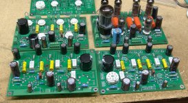
The 6CW5 is a tube originally designed for audio output duty mainly in line operated TV sets. It has a maximum screen voltage of 200 volts and a maximum plate voltage of 250 volts. I have run the GE branded tubes at 230 volts plate and screen with good results (250 volts B+). The data sheet claims 25 watts for a pair with a 3K ohm OPT. I have a 3300 ohm OPT and I am getting 20 to 24 WPC depending on tubes. The data sheet specs 180 mA plate and 23 mA screen current per channel if you don't run the amp into clipping. Bang into clipping and the current can hit 250 mA per channel. This means that the amp can draw up to 500 mA with 6CW5 tubes. This means that the normal octal rectifier tubes can't be used. The board wasn't laid out for silicon diodes, but a pair of diodes can be installed in place of the 5AR4 socket. Look at the board on the left in the photo in post #94. I have not yet found a conventional power transformer that fits there rather odd requirements but I have an amp running with an Antek 1T200 toroid. B+ is 236 volts putting about 215 volts across the tubes. This makes a reliable 16 WPC with my 3300 ohm OPT's and sounds good. Experimentation to find a better solution for the 6CW5 is underway.
I have two amps running right now the 6BQ5 version which is currently running Russian tubes from Ebay. It is using a Hammond 372HX and a pair of my surplus guitar OPTs wired for a 6600 ohm load. This amp has a nice punchy dynamic sound that likes to rock. The other amp has 6CW5's the Antek toroid, and the same pair of surplus OPT's wired for 3300 ohms. These two amps sound very similar.
There are 3 main different types of tubes that will work in this board:
With a little pin changing maybe a 6GK6? Just a thought.
")
With a little pin changing maybe a 6GK6? Just a thought.
The 6GK6 is not a direct drop in to this board. I cosidered adding jumpers to the board to accomodate the 6GK6 and a few other tubes. I even created a test board that let me run 7 different tube types. Yes the 6GK6 works. It also unfortunately allowed me to fry a pair of cathode resistors and make sparks inside the 5AR4 when I left the jumpers in the wrong place and put in some 6HB6's. I decided not to implement the jumpers in the final board since most users will run EL84's and the jumpers just add to the confusion (and burnt parts) level.
For the more experienced and adventureous users out there, after I am done with the instructions I will outline how to modify this board and the Simple SE in some new and not so Simple creative ways. I have a Simple SE running as a single channel 50 watt guitar amp. It flat out screams! I haven't had time to tweak on the sound at all lately and I was dumb enough to take my Stratocaster apart, so those experiments are a long ways off.
will this amp require a matched quad of tubes? Two matched pairs? Will it handle "unmatched" tubes?
This question always starts one of those debates not unlike the $200 power cord or $500 speaker wire debates.
First let me give the text book "good engineering design" answer:
A push pull amplifier including this one will benefit from perfectly matched pairs in each channel. Some enthusiasts believe that all four tubes should be matched.
Now let me give you my opinion about tube matching:
A push pull amplifier will cancel the all of the even numbered harmonics generated in the output stage (not the preceding stages) if it is completly balanced and remains completely balanced for all operating conditions (not trivial). This cancellation will be less than perfect if the two sides of the push pull circuit are not balanced. This means all of the components need to be perfectly balanced for perfect cancellation to occur. The most imperfect components are the tubes, the OPT, and the cathode bias resistors.
Do we need or even want perfect balance? Well all of the happy SE amplifier owners in the world think not since a SE amplifier is by design perfectly unbalanced (half of the amp is missing). As the SE amp owners will attest the second harmonic is musically pleasing and in fact usefull to mask higher order harmonics. A reasonably low amount of fourth harmonic is not usually audible, but higher order harmonics are not considered desirable. Most of the distortion created in an SE amp is indeed second harmonic.
Well if the even harmonics are friendly do we need any balance at all? Yes, we do. A single ended amp runs a steady DC current through the output transformer. This imposes a constant magnetic field on the OPT core. The core of an SE OPT must be far larger than an equal powered P-P OPT and incorporate a gap so thet it doesn't get magnetically saturated. In a P-P amplifier the two tubes both run their DC currents through the OPT, but from opposite directions. This cancels the constant magnetic field IF THE CURRENTS ARE EQUAL! How do we force the two currents to be equal? By using matched components in both sides of the P-P circuitry.
Do the currents need to be perfectly matched? No, and they never will be, and if they were your OPT still isn't perfect. The degree of matching required is greatly depends on the OPT being used. Some OPT's can't tolerate much imbalance. Most can handle some, and a few can operate with 25% mismatch or more. In general a well designed P-P OPT that is specified to handle enough power (20 to 30 watts in this amp) should have no problem dealing with randomly selected output tubes of the same construction. OPT's that are too small (the 10 watt Edcor that I have tried) or were not designed to be OPT's at all (power or mains toroids) will generally require matched tubes, and maybe some component tweaking to work optimally.
Can you actually buy matched tubes? Will they stay matched after continuous use? In most cases sadly the answer to both questions is no! Much of what is being sold as matched pairs or quads (especially on Ebay) simply means that somebody stuck a bunch of tubes in a tube tester and sorted them by the meter readings. This is better than a pair that gave grossly different readings, but bears little meaning on how the tubes will work in your amp.
I believe that a trully matched pair will be matched first by determining the bias voltage needed to get the operating current being used in your particular amp (about 38 mA per tube in the Simple P-P), then matched again for transconductance at the same current. This is how I make matched sets. I used to carefully match up some sets whenever I got a bunch of tubes, but after a lot of use, they didn't stay matched. So maybe it would help to run each tube for say 24 hours first with power applied (burn in), then do the matching. Or maybe test them first, then burn them in, then test again and reject the ones that changed a lot, then match the rest. This still doesn't guarantee that the transfer characteristics of the two tubes are identical, or that they will age the same, but they should be closer than a random pair.
There are some tube vendors that actually do this, but there are many more who don't even understand what I just said.
So do you need (or want) matched sets for the Simple P-P? If you are using reasonably sized OPT's it isn't required. If the tubes can be "matched" (whatever that means) for a reasonable fee (like $1) it certainly wouldn't hurt and may provide some benefit. If the tubes are matched in the manner that I described, and the price isn't too steep (it is a lot of work) it will provide some initial distortion reduction.
What do I do? Well I have a box of 10 cheap Russian tubes that I got from Ebay, two NOS matched sets of Ei "7189A's" and a big bunch of used tubes of several brands and construction. I make an effort to see that I put the same brand and construction in all 4 places in the amp, then I check the cathode voltage. Any tube that is more than .5 volts off from its mate gets changed until I get two that are close, and that is it. The "matched sets" of "7189A's" are neither matched (one pair is off by .75 volt) nor are they real 7189A's. They look and perform just like the $4 Russian tubes that I got on Ebay, which isn't bad at all. All of my amp testing so far has been performed on the first 4 Russian tubes that I pulled from the box and 4 random used 6CW5's that were selected from 5 (one was voted off because of low cathode voltage).
Tubelab:
Thanks for the most excellent and detailed answer to a basic question. I'm going to have to just break down and buy those Morgan Jones books that everyone talks about so that I can learn the basics but I just can't bring myself to cough up the 35 bucks Amazon wants even for the used copies!
So, matched tubes are nice to have, but aren't the end of the world if you can't get them.
Thanks for the info!
...but I just can't bring myself to cough up the 35 bucks Amazon wants even for the used copies!
Go to Pete Millett's site and read some of his free books. There is a three volume set that is very much at the beginner level and then he has Radiotron 4th ed. that is the "bible". The older ARRL handbooks from the 50's have good chapters on basic tube electronics but also how to cut and drill metal and solder wires.
http://www.pmillett.com/technical_books_online.htm
I just can't bring myself to cough up the 35 bucks Amazon wants even for the used copies!
As books go the MJ books are pretty good. I have both books, and I must admit that I have learned quite a bit from them.
Building Valve Amplifiers goes into the mechanics of assembling the amp. Astute readers will notice a similarity between the amplifier shown on page 19 and my Industrial Amp. The similarity is intentional.
Valve Amplifiers goes into the theory and design of tube amplifiers. Some of the information may be over the heads of beginners, but it is all pracitical and applicable. The Simple P-P bears a similarity to Morgans Bevois Valley amp (page 454) and SY's RLD amp. This similarity is not intentional and AFIK the three designs were developed independently, but all based on a simplified Williamson design. I tested at least a dozen different circuits and came to the conclusion that there are several more complicated ways to get similar performance, and several simple ways to get lesser performance, but this circuit is the best way to make a simple P-P amp.
I don't remember how much I paid but I got them from Amazon when they first came out. I figure that it is still cheaper than burnt parts, but not as much fun!
I am getting requests for schematics, board files, parts lists and all of the information needed to make one of these amps. Unfortunately, I don't have it all ready yet, but I am including the schematic and the PDF of the top layer of the PC board.
Thanks for the schematic. Any chance we can see a parts list (component values)? Here's a question about the schematic: L_FB-2 and R_FB-1 seem to tie directly to ground. I'm guessing those aren't actually feedback connection points? Or am I missing something here?
Here's another question: I know the sockets aren't compatible, but any thoughts on whether the circuit would be a good match for small beam tubes, such as the 6V6GT or 6AQ5?
L_FB-2 and R_FB-1 seem to tie directly to ground. I'm guessing those aren't actually feedback connection points? Or am I missing something here?
These terminals work the same way that the Simple SE works. The L_FB and the R_FB are both two terminal screw connectors. The secondary of the OPT is connected to them. In order to close the feedback loop, you need a connection to the cold side of the OPT secondary (the terminals you referred to) as well as the speaker tap 9the other terminals in the same connector).
any thoughts on whether the circuit would be a good match for small beam tubes, such as the 6V6GT or 6AQ5?
Yes, and Yes. I built test amps with both the 6AQ5 (since I have several hundred of them) and the 6V6. Email responses strongly favored the EL84, so that is what I used here. I have another test amp with 6AQ5's and 6AU6's (all pentode design) that works very well, who knows, maybe next year.
How have things been going with testing?
Not much testing going on. I have been building boards (4) and taking pictures at every opportunity. I have about 500 pictures so far. I have started the process of sorting through the pictures and processing the ones that will be used in the manual.
I have about 1 more week before I have to travel. I don't have any exact plans yet other than an apointment for my mother in law in Pittsburgh on OCT 19. I should have all of the pictures and other data necessary for compiling the construction manual during the trip.
There are thousands of components (many still in unopened boxes) piled up that need to be organized before the "bag of parts" kits will be ready. I am guessing that everything could be ready by early November, but I can't forsee all of the "stuff" that seems to happen.
There are 5 boards in this picture. The 2 in the front row are being assembled for the pictures. The two in the second row are both completed working boards. The one in the back row is being partially assembled to shoot detailed pictures of specific components. The assembly line:
Attachments
I'm wondering, would this little amp be driven to full output with a CD/DAC or does it need to be used with a preamplifier?
At this moment, I don't own a working preamp! Yes it works fine connected directly to a CD player, DVD player or iPOD.
I have a few different types and have tried them all in the SimpleSE. They all sound the same...I can't tell any difference. Maybe due to the active plate load, which the SimplePP doesn't have. I can sort-of tell the difference with the VTA-70 board on the Dynaco, at least in the input position.
JJ's are inexpensive, the quality has been consistent for me, and they sound fine to me. To each their own, of course.
JJ's are inexpensive, the quality has been consistent for me, and they sound fine to me. To each their own, of course.
Any suggestions for brands to look for?
I have a big bunch of Sylvania 6201's so I have been using those. I have tried at least a dozen different US made military surplus versions and they do sound similar. There are about 4 different constructions with very slightly different sound characteristics. The only real outlier is the new production JJ. It looks like it was made from leftover 6DJ8 parts. It has a different sound than all of the US made versions and it measures slightly lower in distortion. Many people prefer this sound, but I keep putting the 6201's back in.
If I recall correctly, the Simple P-P will require 12AT7's in the front end. Any suggestions for brands to look for?
My budget picks are:
-GE 5-star 6201's (triple mica gray plates)
-Mullard CV4024 (later production)
Don't have any Sylvania 6201's, but I've never heard anyone say they didn't like them.
Jeff
- Home
- More Vendors...
- Tubelab
- Tubelab Simple P-P