Just an update to the above, after reading Steve Graham's excellent series on building this amp, I've decided to use Mouser instead of Digi Key and I've created a project with all the items in his tutorial.
I’ve also reassessed the transformers, here is what I’m currently thinking of using:
OPTs: Edcor CXPP25-MS-8K
Power: Hammond 372JX
Choke: Hammond 159r
I’m considering the Hammond power transformer over the edcor as it seems to be better value and was recommended by Steve Graham. Using edcor CXPP25-MS-8K as this was recommended a few times in this thread. Will there be an issue mixing brands of transformer? I don’t think there should be but it doesn’t appear to be common.
Just an update to the above, after reading Steve Graham's excellent series on building this amp...
I read that build article a couple of years ago. I strongly suggest that you ignore the part about drilling holes in the board so that it can be used as a drilling template for the chassis.
Instead, its far easier and less risky to the PC board to simply download the PDF template found in post #48. Print it out, then use the board to verify that it is indeed 1:1 with the board (holes line up). Some computer / printer combinations are not exactly 1:1. Most printer or PDF viewer software offer a scaling feature to fix this.
Once you have a 1:1 print out, simply tape it to the chassis and center punch or drill right through the paper.
Thanks that’s a great suggestion, I was a bit leery of drilling holes in the pcb and thought there must be a better way. This is my first attempt building something like this and I intend to follow that series quite closely as he includes detailed instructions for the chassis, volume control etc so if you have any other suggestions or things that could be improved upon please let me know.
I've investigated different pots as I don't particularly like the solution proposed by George in his series to accommodate the too short (7mm) bushing on the alps alpine (cut a largish hole in the front of the 8mm thick chassis, mount the pot on a 3mm cutoff of aluminium then mount this to the chassis with the pot handle sticking through the chassis hole).
I looked for a good pot with a longer bushing that could be fixed directly to the chassis but I couldn't find one.
Now I'm tempted to get a separate case which already has a pot and just skip the volume pot altogether. I could than attach the amp directly to a preamp or variable output DAC without the volume case. Any suggestions?
Last edited:
Question about physically layout...
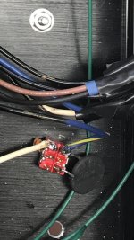
First: I am not using the PCB, but p2p wiring.
Q: How long could the wiring between the output transformers primary windings and the power tubes anode and G2 be, without problems? I will twist anode and G2 for each tube and the runs in my current layout will be apron. 20cm (8 inch)...
")
First: I am not using the PCB, but p2p wiring.
Q: How long could the wiring between the output transformers primary windings and the power tubes anode and G2 be, without problems? I will twist anode and G2 for each tube and the runs in my current layout will be apron. 20cm (8 inch)...
Has anyone tried to use a polypropylene capacitor for the second cap ? (not bypassing the electrolytic with a motor run, but an exclusive cap such as a DC Link or Mundorf TubeCap)
SY wrote in the RLD guide:
"A polypropylene cap in the second position would be a worthwhile upgrade." so wondering if relevant to the SPP too.
SY wrote in the RLD guide:
"A polypropylene cap in the second position would be a worthwhile upgrade." so wondering if relevant to the SPP too.
Has anyone tried to use a polypropylene capacitor for the second cap ? (not bypassing the electrolytic with a motor run, but an exclusive cap such as a DC Link or Mundorf TubeCap)
SY wrote in the RLD guide:
"A polypropylene cap in the second position would be a worthwhile upgrade." so wondering if relevant to the SPP too.
The RLD and SPP are similar designs.
If one takes a careful look at motor run caps many use metalized polypropylene film for the dielectric.
Most motor run caps are indeed polypropylene film caps that are designed to withstand abuse since they are connected directly to the AC line and pass amps of AC current forever.
The parallel combination of a 100 uF ASC motor run cap and a 100 uF Panasonic electrolytic showed the best overall performance at bypassing a dirty (purposefully created) power supply line from 5 Hz to 100 KHz in real world testing that I did probably 15 years ago. Components have changed considerably since then, some for better, and some for worse.
I'm sure that a good poly cap alone could do nearly as good, and maybe even better. The electrolytic alone lost performance above 25 KHz or so.
Whether or not any of this was audible is unknown, but adding that ultra low ESR poly cap across the electrolytic did make a noticeable improvement in transient response, both measured, and heard in an SSE based amp. A similar added poly cap in the SPP makes an improvement too.
In order to get good bass response the total capacitance of the second cap needs to be in the 100 uF or greater range. A small poly cap of 100 uF may not be available, hence the parallel electrolytic and poly caps.
Thanks for the detailed reply George.
I ordered one of those 100uF Mundorf polypropylene TubeCaps (at a more reasonable price to what it is being sold currently).
I'll be using SS rectifiers with 100uF (electrolytic) - L - 100uF (PP) in the PSU.
I could add electrolytic to the PCB later if more bulk capacitance is needed.
Is there a way to measure whether more capacitance is needed in the PSU?
I have not tried a 4.7K resistor in the SPP. In theory it should not have an effect.
Some new production tubes may start to draw grid current in the -1 to 0 grid volts range, so an excessively large grid resistor could cause a slight reduction in maximum power output, but I have seen far larger grid resistors used in some amps.
Some new production tubes may start to draw grid current in the -1 to 0 grid volts range, so an excessively large grid resistor could cause a slight reduction in maximum power output, but I have seen far larger grid resistors used in some amps.
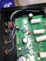
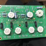
I'm nearing completion of the SPP amp kit. It's not been turned on yet and I'm debating whether to connect the volume pot or not.
I've been following Steve Grahams excellent instructions and I'd highly recommend anyone who is planning to take this project on to do the same if like me this is your first attempt at something like this.
I made a lot of mistakes and ended up doing things a little bit differently as a result. I've written a few of them up here in case anyone in Europe is planning to make one of these.
I need a 230V power transformer. Originally I decided to use the 372JX but decided to use a 372HX instead as there was few weeks delay for stock to arrive and the mounting holes were the same as the 272HX described in Steve Grahams articles.
Output transformers were 1650FA. I bought the transformers from don-audio.com.
Tubes, JJ ECC81, JJ EL84, Sovtek 5AR4, from hificollective.co.uk
I created a mouser project with the parts I ordered
I also drilled a counter sunk hole into the back of the front panel to mount an AudioNote 100K (from hifi collective) pot instead of mounting it on a separate piece as described in Steve's articles. I drilled this and the holes for the tubes in the chassis with a drill press, Steve seemed to do it with a hand drill but this must have been very difficult...
I printed out a picture of the schematic, and sized it to exactly the same size of the PCB instead of drilling holes in the PCB as suggested by Steve.
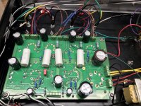
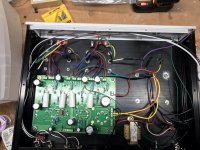
Mistakes I made :/
1) I thought the 159R chock would fit in the chassis in reality it was way to big so I got the 156R instead
2) I put the power amp in the wrong way (there are differences between the 272JX and 373HX I didn't take into account)
3) I bought several different capacitors as the ones I wanted were out of stock however some of these were over 25mm high and didn't fit in the case
4) Steve forgot to add 2m of red 18 or 20 guage wire to the order, so I didn't have this
5) I wasn't careful with the top panel and realised afterwards that the mounting holes aren't symmetrical, therefore in order to create the case I had to reverse the position of the circuit board, meaning that the connections to the front and rear panel are all opposite to Steve's. I also had to move the on/off switch as a result as it was next to the power input. However in some ways I prefer this layout as everything is closer to it's natural connection point with the board
6) I must have gotten sloppy with the placement as one of the 5 screws supporting the PCB doesn't line up correctly.
What I would do differently:
I'd buy the hook up cables from hificollective.co.uk
instead of the ebay seller mentioned by Steve as they have them in stock and I ordered the tubes, RCA connections, and tube sockets from them.
I'm debating using an external volume box, I mentioned this earlier in this thread. As it's more versatile and I don't like the long hookup cables to connect the pot. I plan to connect this to a raspberry pi running an Allo AC/DC so the need for a manual volume is limited. I haven't connected the volume pot so this is still an option.
I'd buy the bigger 372HX power transformer... because why not?
Any suggestions regarding the volume pot?
I've been following Steve Grahams excellent instructions and I'd highly recommend anyone who is planning to take this project on to do the same if like me this is your first attempt at something like this.
I made a lot of mistakes and ended up doing things a little bit differently as a result. I've written a few of them up here in case anyone in Europe is planning to make one of these.
I need a 230V power transformer. Originally I decided to use the 372JX but decided to use a 372HX instead as there was few weeks delay for stock to arrive and the mounting holes were the same as the 272HX described in Steve Grahams articles.
Output transformers were 1650FA. I bought the transformers from don-audio.com.
Tubes, JJ ECC81, JJ EL84, Sovtek 5AR4, from hificollective.co.uk
I created a mouser project with the parts I ordered
I also drilled a counter sunk hole into the back of the front panel to mount an AudioNote 100K (from hifi collective) pot instead of mounting it on a separate piece as described in Steve's articles. I drilled this and the holes for the tubes in the chassis with a drill press, Steve seemed to do it with a hand drill but this must have been very difficult...
I printed out a picture of the schematic, and sized it to exactly the same size of the PCB instead of drilling holes in the PCB as suggested by Steve.
Mistakes I made :/
1) I thought the 159R chock would fit in the chassis in reality it was way to big so I got the 156R instead
2) I put the power amp in the wrong way (there are differences between the 272JX and 373HX I didn't take into account)
3) I bought several different capacitors as the ones I wanted were out of stock however some of these were over 25mm high and didn't fit in the case
4) Steve forgot to add 2m of red 18 or 20 guage wire to the order, so I didn't have this
5) I wasn't careful with the top panel and realised afterwards that the mounting holes aren't symmetrical, therefore in order to create the case I had to reverse the position of the circuit board, meaning that the connections to the front and rear panel are all opposite to Steve's. I also had to move the on/off switch as a result as it was next to the power input. However in some ways I prefer this layout as everything is closer to it's natural connection point with the board
6) I must have gotten sloppy with the placement as one of the 5 screws supporting the PCB doesn't line up correctly.
What I would do differently:
I'd buy the hook up cables from hificollective.co.uk
instead of the ebay seller mentioned by Steve as they have them in stock and I ordered the tubes, RCA connections, and tube sockets from them.
I'm debating using an external volume box, I mentioned this earlier in this thread. As it's more versatile and I don't like the long hookup cables to connect the pot. I plan to connect this to a raspberry pi running an Allo AC/DC so the need for a manual volume is limited. I haven't connected the volume pot so this is still an option.
I'd buy the bigger 372HX power transformer... because why not?
Any suggestions regarding the volume pot?
Attachments
Last edited:
Hi, I have a Simple PP pcb and was thinking I'd like to do a push-pull EL86 triode version, using a pair of Russian 6P43P-E per channel.
I have a Triad toroid 220VCT power transformer for the plate supply, and a good 6.3VCT transformer for the heaters. I also have a pair of old OPTs from a Dynaco ST70, which are supposed to have about a 4.5k ohm plate-to-plate primary impedance. That should be about right for push-pull EL86-triodes.
So the question -- What driver tube to use? The problem of course is that the B+/plate supply will be only about +270VDC, which is rather low for a cathodyne.
Has anyone tried this?
6DJ8?
6BQ7?
6FQ7?
6GU7?
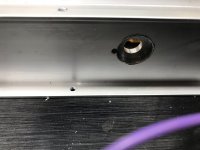
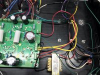
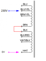
I have one issue that I'm a bit confused about. Originally the 272JX was used which has black (125V) and white (0V) leads from the primary. I've attached a screenshot showing how these were wired to the power switch.
However it appears that the neutral lead of the AC input (white wire) is connected to the black primary winding (125V) though the inrush limiter (large black thing, looks like a capacitor). Similarly the live lead of the AC Input (Black) is connected to the white (0V) lead of the primary.
Is this correct (in my mind it seems the live lead of the AC should be connected to the 125V primary) and can I simply replace the black lead of the 272JX with the blue/yellow lead of the 372HX, as shown?
Attachments
Last edited:
In the instructions I flipped the black and white on the primary for no good reason that I can recall.
I assume you have 230 AC power. In this case it might be best connect the white to the neutral and the line lead to the BLUE wire (which is likely the 240 volt connection). Use the blue for first start-up and measure your filament voltages. If they are a bit low then switch over to the BLUE/YELLOW. Better to start a bit too low than too high. Be sure to securely (double?) insulate the unused transformer wires.
Hope this helps, good luck with your build.
Steve
In the instructions I flipped the black and white on the primary for no good reason that I can recall.
I assume you have 230 AC power. In this case it might be best connect the white to the neutral and the line lead to the BLUE wire (which is likely the 240 volt connection). Use the blue for first start-up and measure your filament voltages. If they are a bit low then switch over to the BLUE/YELLOW. Better to start a bit too low than too high. Be sure to securely (double?) insulate the unused transformer wires.
Hope this helps, good luck with your build.
Steve
Thanks Steve, I really appreciate the reply and your excellent series of building instructions.
I’ll unsolder and switch the primary leads in that case.
Using the 240V primary tap seems like a good idea (you’re correct it’s the blue one)
Unfortunately I installed the 300 ohm resistors, damn I’m not sure why I did that. It’s a pain to take up the board and resolder them on the opposite side but I might be able to do it through the tube holes. I do have 360 ohm resistors, so I’m not sure why I decided to use the 300 ohm resistors but I remember thinking about it
Attachments
Last edited:
- Home
- More Vendors...
- Tubelab
- Tubelab Simple P-P