If you are really interested in some of the articles in this website, let me know and I might be able to do some translation for you. The translation might not be perfect but at least I can practice my English.JasonL said:Every time i look at this web-page i spend hours on it looking and browsing. i wish i could read it in english. maybe order some stuff from them there boards look awesome. http://www.diyzone.net

Hats Off To Joe
Hi
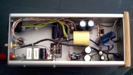
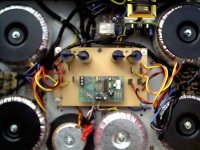
I built monobloc GC's 2 weeks a go using Thorsten's ultimate power supply..These have 4 250VA Tx (2 per channel ) secondries are 40 volts but primaries are in series thus giving a secondry 0f 20Volts.
I thought they were pretty much finished the sound these produce is outstanding driving B&W CDM 1NT's..
Well I couldn't sit back without trying Joe's buffer stage..Phew what a great upgrade,It's hard to believe any improvement could be had,but hell the sound is just outstanding..
I have used single Tx for the HT and filament supplies but are split with their own brigdes/filters..
B+ = 39V
DC Offset 3.1mV
Ripple 1.2mV AC
Valve current =3.9mA
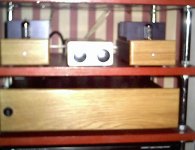
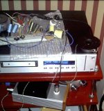
Here are some crap pictures of work in progress( should have some HiRez by the weekend of internals ..
Regards
Peter
Hi
I built monobloc GC's 2 weeks a go using Thorsten's ultimate power supply..These have 4 250VA Tx (2 per channel ) secondries are 40 volts but primaries are in series thus giving a secondry 0f 20Volts.
I thought they were pretty much finished the sound these produce is outstanding driving B&W CDM 1NT's..
Well I couldn't sit back without trying Joe's buffer stage..Phew what a great upgrade,It's hard to believe any improvement could be had,but hell the sound is just outstanding..
I have used single Tx for the HT and filament supplies but are split with their own brigdes/filters..
B+ = 39V
DC Offset 3.1mV
Ripple 1.2mV AC
Valve current =3.9mA
Here are some crap pictures of work in progress( should have some HiRez by the weekend of internals ..
Regards
Peter
Attachments
protos said:Everybody seems happy with their tube buffers in their GC's and the general opinion is that they sound better than the minimal GC.I think comparing a fet or ic buffered GC to Joe's tubed version would be more fair though and it would be much simpler to implement.
Anyone following my postings will know that I have recognised the fet approach as valid. Pedja has done it to good effect. Even an IC, a very good one - OPA 627, has been tried by Nuuk. He seems to like it too, but that I would regard as last option.
But after doing it as a fet, then it would be good if someone could then go ahead and do the tube buffer and let us know their impressions/differences.
Whatever the buffer, don't forget the LPF.
Joe R.
Everybody seems happy with their tube buffers in their GC's and the general opinion is that they sound better than the minimal GC.I think comparing a fet or ic buffered GC to Joe's tubed version would be more fair though and it would be much simpler to implement.
I'm not sure what the point is here? I did an IC buffer as Joe says and that has demonstrated the improvement that a buffer/LPF makes to the basic GC. Having heard that improvement with an IC, and having talked with PeterM who has done a tube buffer, I am now happy to go for broke, and do the tube buffer/LPF.
The word 'fair' implies some sort of competition here when really we are all on the same side and trying to get the best sound from our amps! And I can tell you that the standard IGC is not as good as one with an IC buffer and LPF!

It's exactly because I think that a buffered GC is much better than a non-buffered one that I said it wouldn't be be a "fair" comparison . I have used a Pass BOSOZ pre which is essentially a fet buffer as well as a DRV134 balanced line driver stage which is essentially a chip buffer and I think the results are much better sonically than the minimal GC.I have not tried LPF as applied by Joe but I am thinking of doing so if somebody can help calculate the values for a balanced input.The question thus is whether a tube buffer is better than a fet or chip buffer.
protos said:...but I am thinking of doing so if somebody can help calculate the values for a balanced input.The question thus is whether a tube buffer is better than a fet or chip buffer.
OK, give the values of the input 'feedback resistor' that feeds the inverted (-) input and I will give you the LPF values. This resistor affects the time constant, which should be 30-31uS (not the earlier value I miscalculated). If you are using 10K here, may I suggest that you up the main feedback resistor to 300K or 330K. Get back to me.
Whether a tube buffer is better than an IC buffer, Nuuk will no doubt enlighten us... go Nick!!!

Joe R.
Hi
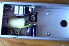
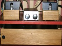
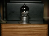
Another not so good picture :-(
I have not heard a FET buffered GC but hell Joe's valve offering is a major improvement to what was a good sounding amp..
Having chated with Nick (NUUK) for almost 2 hours last evening it does appear a buffer is a major improvement over a standard GC.Nick as taken the challenge to go valve buffer (even better when 90% of the parts are on offer)..But that's what i find great about DIY you can share..
Regards
Peter
Attachments
protos said:This is the network I am using.
An externally hosted image should be here but it was not working when we last tested it.
These are the values/circuit I'd recommend.
Note a few things:
The 'AC Voltmeter' indicates gain as source is 1V. That means with the values shown overall gain = 32.97 or 30.4dB.
That means virtually no feedback above 200KHz due to the internal compesensation. Because of this internal arrangement the 90 degrees phase lag is flat up to 200KHz but above that it lags further. If it lags beyond 90 it is detrimental IF there is feedback at those frequencies.
The above circuit assumes Lo-Z source. If source impedance is 200 Ohm, then reduce 2K2 to just 2K, etc.
Try it and let us know!
Joe R.
Just if I may amend an ealier posting:
Please note earlier I set the Sig Gen to +1V/-1V and thus the gain is incorrect as shown by AC meter. Once corrected to +1.4V/-1.4V to give RMS output value to equal gain = 46, that is slightly above +33dB.
I would still go with that value as this is the gain I use in the JLTi. But 390K will give you +30dB. So somewhere in the range of 390K to 560K should be OK.
Joe R.
An externally hosted image should be here but it was not working when we last tested it.
Please note earlier I set the Sig Gen to +1V/-1V and thus the gain is incorrect as shown by AC meter. Once corrected to +1.4V/-1.4V to give RMS output value to equal gain = 46, that is slightly above +33dB.
I would still go with that value as this is the gain I use in the JLTi. But 390K will give you +30dB. So somewhere in the range of 390K to 560K should be OK.
Joe R.
G'day Joe. I'm getting a shopping list together to build a valve buffered IGC based on your design and I have been re-reading your DIY page.
I have one question about the filter components. The values that you have in your circuit diagram are 4k7/1n3 which according to my calculations comes out at 25,505Hz. But I thought that the idea was to filter out anything above 32K. Am I right in thinking that the filter starts at 25,505 and cuts eveything off by the time we get to 32K?
We don't seem to be able to get 1n3 here in the UK (at least not from Farnell) so I presume that 5K1/1n2 will do the job just as well (and I'll get some other values to try as well)
Now back to fridge for a cold drink - it's hotter here than a hot day in Laverton, WA!
") ))
))Banned
Joined 2002
- Status
- This old topic is closed. If you want to reopen this topic, contact a moderator using the "Report Post" button.
- Home
- Amplifiers
- Chip Amps
- Tube with Power IC Output Stage - JLTi