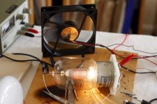
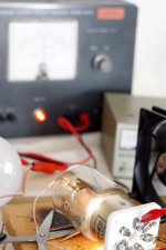
The 4E27's plate needs to glow red to getter itself. When these tubes are running in transmitting or modulator service, this is a normal condition. If you can get the plate to glow red for a while, there is a good chance it will come back. If it had too much air in bulb, the filament would have let go already. You will need to cool the seals of the bulb so the Covar or Dumet does not fail. A large muffin fan should do the trick. When that tube is in it's intended service, the socket is pressurized by a blower fan. The air escapes through the holes in the aluminum ring around the base of the tube. These tubes can convection cool but need to be run softer.
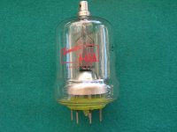
Here is an 826 that I re-gettered.
Here is an 826 that I re-gettered.
An externally hosted image should be here but it was not working when we last tested it.
After a whole night of 115V AC through it, the current drawn dropped to about 0.28mA AC. However, now when I give it DC on the anode (triode strapped) the current does not go above 5mA. The purplish glow is more diffuse and only happens around 450V DC. Perhaps this is a sign that its less gassy and that I should continue with the AC treatment.
@panoramic Nice glow on the 826. The question is how do it get the 4e27 to glow like that?
@panoramic Nice glow on the 826. The question is how do it get the 4e27 to glow like that?
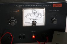
Hello Ikoflexer. If you want to get the plate warm, you will need a variable powersupply and a variable Negative supply. Great care must be taken, as lethal Voltages are required to do this process. If your not comfortable with this "don't do it!" This process is only good for certain types of transmitting tubes and modulator service tubes with specially coated plates.This will not work with regular audio tubes, such as indirectly heated types like the 6L6, KT series, or any smaller bottles with getter spots on the glass.
Tie the the screen grid and the suppressor grid to the plate. Give the tube about 450 Volts on the plate (between plate and filament) The variable power supply should have a current limit set just incase the tube runs away. Start the tube with a very high negative supply on the control grid, so bring the control grid negative a few hundred volts. Slowly turn the control grid more positive by reducing the negative supply voltage. The reason to start the negative voltage so high, is because the tube will not act normal when there is air in the bulb. Eventually you will get to a point where the tube will start to draw current, this is where you must take care not to draw to much or the tube will ionize. Slowly reduce the bias (negative control grid voltage) until you start to see the plate glow faintly red. You must monitor the tube through this whole process because at any time it may ionize the air inside. If it does, shut the supply off quickly as it will draw incredible current. Turn the bias back up to the max and start over again. You will get to feel where the point is, at how far you can push the tube before ionization occurs. The whole idea is to just get the plate faintly red and let it baste there for a while. If your tube recovers, eventually you will be able to make the tubes plate glow orange for a very short period and no ionization will occur. Be warned, This is a finicky resto process and you need to have a current limited supply. You also must be fast on the "off switch." Use a good cooling fan for the tube in this process.
Tie the the screen grid and the suppressor grid to the plate. Give the tube about 450 Volts on the plate (between plate and filament) The variable power supply should have a current limit set just incase the tube runs away. Start the tube with a very high negative supply on the control grid, so bring the control grid negative a few hundred volts. Slowly turn the control grid more positive by reducing the negative supply voltage. The reason to start the negative voltage so high, is because the tube will not act normal when there is air in the bulb. Eventually you will get to a point where the tube will start to draw current, this is where you must take care not to draw to much or the tube will ionize. Slowly reduce the bias (negative control grid voltage) until you start to see the plate glow faintly red. You must monitor the tube through this whole process because at any time it may ionize the air inside. If it does, shut the supply off quickly as it will draw incredible current. Turn the bias back up to the max and start over again. You will get to feel where the point is, at how far you can push the tube before ionization occurs. The whole idea is to just get the plate faintly red and let it baste there for a while. If your tube recovers, eventually you will be able to make the tubes plate glow orange for a very short period and no ionization will occur. Be warned, This is a finicky resto process and you need to have a current limited supply. You also must be fast on the "off switch." Use a good cooling fan for the tube in this process.
At nominal 5V on the filament the tube doesn't want to pass more than 1mA of current even at 450V DC on the anode, with +30V on the grid. But I'm not giving up yet. I increased the filament voltage to 10V. Now the tube got a nice red plate with 0V on the grid and about 100V on the plate. I'll let it bake like this for a while. It's incredible how tough this tube is. I even tried 12V on the filament, and it didn't burn. Surely it wouldn't have a long life if operated on high filament voltage.
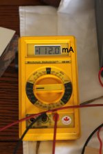
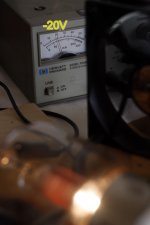
This is what it looks like, at the moment. About 245V on the plate, -20V on the grid, and about 9.5V on the filament (instead of 5V), ends up drawing about 112mA and the plate is red.
Attachments

Yup, stay away from anything that isn't Eimac. And even then, stay away from any Eimac with green glass on the base of the tube. Eimac 4E27's have an open socket base so you can see the bottom of the glass, Same goes for 4-65A's too. This is the voice of experience speaking.
It's inside the glass it's self. And only on the older Eimacs. I have no idea why they colored the glass green, only that virtually all of that vintage has seal problems. But usually Eimac tubes are much better then HKs.Is the green stuff on the inside?
This was usually made w/DHT tubes, I believe Oxide costed Catrhodes dont apply.In broadcasting, a fairly standard practice for squeezing an extra bit of life out of a very expensive tube whose emissions have dripped off is to up the fillament voltage say 10% and let it cook about 12 hrs with no HV applied. This seems to somehow free up a bit more cathode material. At multiple thousands of dollars each even an extra six months of time is worth a little effort.
My question is has anybody tried a similar practice with audio tubes and if so what were the results?
Doc
Also in transmiting stations was commom reduce the heating Tension abit to save the Thorium;
- Status
- This old topic is closed. If you want to reopen this topic, contact a moderator using the "Report Post" button.
- Home
- Amplifiers
- Tubes / Valves
- Tube rejuvination