The 6SN7 preamp works. End of story.
No, Frank - he actually had trouble measuring it correctly. Placing the meter on the cathodes of the 6SN7 with that big capacitor sitting there is going to mess up any reading you take. If he had disconnected the connection to the capacitor, the bias value would have read "normal".
I hope that clears up any remaining mystery.
I wouldn't expect you, Joe, or hardly anyone else on this forum to say a simple RC coupled amp (with a cathode follower, none the less!!!) sounds "exceptional". This is par for the course.
Joel
fdegrove said:Well, Burnedfingers/Joe built it but had difficulties getting it to bias correctly.
No, Frank - he actually had trouble measuring it correctly. Placing the meter on the cathodes of the 6SN7 with that big capacitor sitting there is going to mess up any reading you take. If he had disconnected the connection to the capacitor, the bias value would have read "normal".
I hope that clears up any remaining mystery.
...from the feedback he gives it doesn't sound all that exceptional
I wouldn't expect you, Joe, or hardly anyone else on this forum to say a simple RC coupled amp (with a cathode follower, none the less!!!) sounds "exceptional". This is par for the course.
Joel
I've built the Waarde circuit that fdegrove mentioned and gave a link for. Since then I've made many changes to it, but it really is nice sounding. It's simple, sounds good and can drive difficult loads, like capacitive source-followers.
I'd reccomend it, if you want something great at a low starting cost...
I'd reccomend it, if you want something great at a low starting cost...
AREN VAN WAARDE.
Hi,
I'd welcome any comments on the changes you made, JoeBob.
If you care to share them, that is.
Cheers,")
Hi,
Since then I've made many changes to it, but it really is nice sounding. It's simple, sounds good and can drive difficult loads, like capacitive source-followers
I'd welcome any comments on the changes you made, JoeBob.
If you care to share them, that is.
Cheers,
lonk
Could you post a link, please? Thanks.
JoeBob said:I've built the Waarde circuit that fdegrove mentioned and gave a link for. Since then I've made many changes to it, but it really is nice sounding. It's simple, sounds good and can drive difficult loads, like capacitive source-followers.
I'd reccomend it, if you want something great at a low starting cost...
Could you post a link, please? Thanks.
fdegrove posted it in post #31.
http://headwize2.powerpill.org/projects/showproj.php?file=waarde1_prj.htm
It's written that it's a headphone amp, but that just means it can drive low impedence loads.
http://headwize2.powerpill.org/projects/showproj.php?file=waarde1_prj.htm
It's written that it's a headphone amp, but that just means it can drive low impedence loads.
Koinichiwa,
Actually, Steve I'm disappointed. We are dealing with two different "gains" here. One is the so-called "noise-gain". It determines the stability of the circuit.
If you where to replace the 220k input resistor with a 20k resistor the circuit would have a gain of around 21db (inverting), as drawn the INPUT signal is amplified by exactly 1 or in other terms shows 0db gain (inverting). And no, there is not a "voltage divider" at work, here is why....
In an inverting circuit the negative input forms in effect a "virtual ground". The negative input is forced to remain at the same potential as the positive input (which is at zero level all the time) by the operation of negative feedback.
So, the 22k resistor to ground does NOT form a voltage divider with the 220K input resistor. Instead the 220K input resistor injects a given current (given by the input voltage) into the summing junction (negative input) which is opposed by an equal but opposite change in current through the output to neghative input resistor.
Should both resistors have the same value the output Voltage MUST be the same as the input voltage, while the negative input remains at 0V all the time. As there is no voltage on the negative input (actually there is - but only if the system is unbalanced and tries to have the output voltage catch up with input voltage), at least not when the circuit is "in sync" there is no current through the 22k resistor.
WHERE the 22k resistor comes in is for the inherent noise of the circuit, which actually will cause the circuit to oscillate UNLESS the gain for this noise itself is sufficient to ensure stability. In effect, the 22k resistor is part of one loop together with the 220k feedback resistor, the 220k input resistor and the 220k feedback resistor is part of another current loop. I know this not that intuitive or that easy to understand, but is actually quite clear to anyone who EVER has at leaste skimmed Electronics 101 - feedback loop stability.
Sayonara
PS, to go on topic, my recommendation for a Line Preamplifier to go with a "Unitygainclone" would be one halve of a 5687, 10K anode load, -2.7V fixed grid bias (3V lithium Cell via 470k to grid, 4M7 to ground), 100nF input coupling capacitor, 220nF output coupling Cap to the 220k input resistor, +B 250V.
It does not get much better and simpler than that.
Alternatively a 220 ohm cathode resistor and a 220uF Cathode bypass capacitor may be used in lieu of the input capacitor and battery grid bias. Having tried both I find it much easier and cheaper to get a good quality 100nF capacitor than a good quality 220uF capacitor, but that's just me.
Steve Eddy said:
Apparently he's using this circuit:
<center>
<img src="http://www.diyaudio.com/forums/attachment.php?s=&postid=112202">
</center>
Although the input resistor is the same value as the feedback resistor (220k), it's actually in parallel with the 22k shunt resistor at the inverting input. So you have 220k||22k, which comes to 20k. So the voltage gain is 220k/20k which comes to 11 (about 21dB)
And that 220k/22k combination also forms a 1:10 voltage divider so that the input signal is attenuated by a factor of 10, or 21dB.
But the fact remains that the LM-3875 is functioning <b>EXACTLY</b> as if you were to remove the 22k resistor and replaced the 220k input resistor with a 20k resistor.
Actually, Steve I'm disappointed. We are dealing with two different "gains" here. One is the so-called "noise-gain". It determines the stability of the circuit.
If you where to replace the 220k input resistor with a 20k resistor the circuit would have a gain of around 21db (inverting), as drawn the INPUT signal is amplified by exactly 1 or in other terms shows 0db gain (inverting). And no, there is not a "voltage divider" at work, here is why....
In an inverting circuit the negative input forms in effect a "virtual ground". The negative input is forced to remain at the same potential as the positive input (which is at zero level all the time) by the operation of negative feedback.
So, the 22k resistor to ground does NOT form a voltage divider with the 220K input resistor. Instead the 220K input resistor injects a given current (given by the input voltage) into the summing junction (negative input) which is opposed by an equal but opposite change in current through the output to neghative input resistor.
Should both resistors have the same value the output Voltage MUST be the same as the input voltage, while the negative input remains at 0V all the time. As there is no voltage on the negative input (actually there is - but only if the system is unbalanced and tries to have the output voltage catch up with input voltage), at least not when the circuit is "in sync" there is no current through the 22k resistor.
WHERE the 22k resistor comes in is for the inherent noise of the circuit, which actually will cause the circuit to oscillate UNLESS the gain for this noise itself is sufficient to ensure stability. In effect, the 22k resistor is part of one loop together with the 220k feedback resistor, the 220k input resistor and the 220k feedback resistor is part of another current loop. I know this not that intuitive or that easy to understand, but is actually quite clear to anyone who EVER has at leaste skimmed Electronics 101 - feedback loop stability.
Sayonara
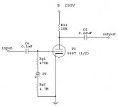
PS, to go on topic, my recommendation for a Line Preamplifier to go with a "Unitygainclone" would be one halve of a 5687, 10K anode load, -2.7V fixed grid bias (3V lithium Cell via 470k to grid, 4M7 to ground), 100nF input coupling capacitor, 220nF output coupling Cap to the 220k input resistor, +B 250V.
It does not get much better and simpler than that.
Alternatively a 220 ohm cathode resistor and a 220uF Cathode bypass capacitor may be used in lieu of the input capacitor and battery grid bias. Having tried both I find it much easier and cheaper to get a good quality 100nF capacitor than a good quality 220uF capacitor, but that's just me.
Kuei Yang Wang said:PS, to go on topic, my recommendation for a Line Preamplifier to go with a "Unitygainclone" would be one halve of a 5687, 10K anode load, -2.7V fixed grid bias (3V lithium Cell via 470k to grid, 4M7 to ground), 100nF input coupling capacitor, 220nF output coupling Cap to the 220k input resistor, +B 250V.
Could you post a schematic, please? Thanks.
Koinichiwa,
Almost. Remove the 4M7 (4.7 Megaohm) resistor from the ground connection of the battery and place it from the Grid to ground.
The rest is fine. If you want to drive a load other than 220k from this circuit the output coupling capacitor needs to be increased in value.
Sayonara
JAZZ2250 said:Maybe like this?
Almost. Remove the 4M7 (4.7 Megaohm) resistor from the ground connection of the battery and place it from the Grid to ground.
The rest is fine. If you want to drive a load other than 220k from this circuit the output coupling capacitor needs to be increased in value.
Sayonara
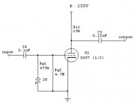
Kuei Yang Wang said:Remove the 4M7 (4.7 Megaohm) resistor from the ground connection of the battery and place it from the Grid to ground.
The rest is fine. If you want to drive a load other than 220k from this circuit the output coupling capacitor needs to be increased in value.
Kombangwa,
I hope the following is correct.
BTW, how can I calculate the coupling capacitor value? In my case, I replaced 220k resistors with 47k's.
Domo Arigato.
Attachments


Koinichiwa,
Wrong on both accounts.
The 4M7 resistor makes sure that the grid voltage is -2.7V and not -3V (and yes, the difference is audible).
As for the Output impedance, the 5687 operated as shown here has around 2300 Ohm anode impedance. With the Anode Load resistor in parallel the effective output impedance will be around 1k8.
That is not terribly low but just fine to drive sensible loads (10k//1nF is just fine with a -3db point at around 80KHz) if the coupling capacitor is sufficiently sized.
For simplicity, Capacitance in uF = 50 / Load (Kohm), use nearest preferred value.
Sayonara
Joel said:Jazz, the 4.7M is doing nothing whatsoever there. Remove it completely.
Then you'll have a nice preamp with a sky-high output impedance.
Wrong on both accounts.
The 4M7 resistor makes sure that the grid voltage is -2.7V and not -3V (and yes, the difference is audible).
As for the Output impedance, the 5687 operated as shown here has around 2300 Ohm anode impedance. With the Anode Load resistor in parallel the effective output impedance will be around 1k8.
That is not terribly low but just fine to drive sensible loads (10k//1nF is just fine with a -3db point at around 80KHz) if the coupling capacitor is sufficiently sized.
For simplicity, Capacitance in uF = 50 / Load (Kohm), use nearest preferred value.
Sayonara
Kuei Yang Wang said:...The 4M7 resistor makes sure that the grid voltage is -2.7V and not -3V (and yes, the difference is audible).
If a .3V difference is audible to you, then where are you going to find a battery that delivers exactly 3V, and over its useful lifespan? Shouldn't there be a mechanism to adjust for drift?
cheers
Joel
Koinichiwa,
The Lithium Button Cells I have used in several circuits like this show in essence shelf life (being discharged through > 5MOhm. New they measured actually 3.12V and after two years they measured 3.12V. So no drift I could measure.
The 0.3V is audible btw. because the Valves transconductance as operated is around 8mA/V or a 20% shift in operating current and anode voltage, approximatly.
Sayonara
Joel said:
If a .3V difference is audible to you, then where are you going to find a battery that delivers exactly 3V, and over its useful lifespan? Shouldn't there be a mechanism to adjust for drift?
cheers
Joel
The Lithium Button Cells I have used in several circuits like this show in essence shelf life (being discharged through > 5MOhm. New they measured actually 3.12V and after two years they measured 3.12V. So no drift I could measure.
The 0.3V is audible btw. because the Valves transconductance as operated is around 8mA/V or a 20% shift in operating current and anode voltage, approximatly.
Sayonara
Kuei Yang Wang, I guess this is as good a place to ask, the batteries you use, what Ah rating do they have, and how long do they last? I know the amperage being sucked out of them is going to be low, but won't they be drained 24/7? I was thinking of biasing my tubes in such a fashion, but was worried I'd be changing batteries all the time.
BATTERIES.
Hi,
If I may replace TL for a minute:
Doesn't matter, you have neglectable power consumption so as TL stated the lifespan is the same as the shelflive for these batteries.
OK, if you must...expect to replace the 5$ batteries every 2 years at most.
Look at it this way: the battery is likely consuming less than that Rolex you're wearing so...
Cheers,
Hi,
If I may replace TL for a minute:
Kuei Yang Wang, I guess this is as good a place to ask, the batteries you use, what Ah rating do they have, and how long do they last? I know the amperage being sucked out of them is going to be low, but won't they be drained 24/7? I was thinking of biasing my tubes in such a fashion, but was worried I'd be changing batteries all the time.
Doesn't matter, you have neglectable power consumption so as TL stated the lifespan is the same as the shelflive for these batteries.
OK, if you must...expect to replace the 5$ batteries every 2 years at most.
Look at it this way: the battery is likely consuming less than that Rolex you're wearing so...
Cheers,
Kuei Yang Wang said:Actually, Steve I'm disappointed. We are dealing with two different "gains" here. One is the so-called "noise-gain". It determines the stability of the circuit.
Yes. I'm aware of that.
If you where to replace the 220k input resistor with a 20k resistor the circuit would have a gain of around 21db (inverting), as drawn the INPUT signal is amplified by exactly 1 or in other terms shows 0db gain (inverting). And no, there is not a "voltage divider" at work, here is why....
Aye. I let myself get too focused on the fact that the 220k input resistor and the 22k resistor were in parallel and neglected the fact that the 22k resistor does not carry any signal current.
Thanks for forcing me to take a step back.
se
- Status
- This old topic is closed. If you want to reopen this topic, contact a moderator using the "Report Post" button.
- Home
- Amplifiers
- Chip Amps
- tube preamp to mate with Gainclone