Attempting a tube phono stage. Since I am pretty new to building tube circuits, I would welcome some opinions on the circuit that I have chosen. I found this one one online and it seems to be the simplest one I have seen. Appears to be a zero feedback loop design also. How do you all think it will sound? Does anyone recommend any changes or a completely different design?
Attachments
Hi, it will work.... BTW it uses a feed back design for the equalization. My biggest issue is the power supply. IMO not nearly enough filtering but then I am pretty well known as being very unhappy with any hum or noise. Generally as a starter project, not too bad. Be careful on the grounding arrangement and layout in general. Both areas can quickly turn a good project into a real "hum dinger"")
Does anyone recommend any changes or a completely different design?
This type of feedback network has poorly controlled LF gain, so the equalization
below 100Hz will vary significantly with different tubes, and with tube ageing.
The second tube uses what is called "grid leak bias" which some consider
to be a poor design option.
Last edited:
Thanks Bruce. I do agree and plan on beefing up the power supply filters. My biggest concern is the preamp circuit itself, particularly the RIAA eq part. Looks like it uses only 1 resistor and two capacitors, I thought that in simplist form there are two resistors and two capacitors required for RIAA. But maybe I am wrong. Just want to get opinions before I spend the time and money to build.
This type of feedback network has poorly controlled LF gain, so the equalization below 100Hz
will vary with different tubes, and with tube aging.
Is there something you suggest I can do to correct that? Plan on using either two JJ 12ax7 or an eh12ay7 as input and then 12ax7 as output.
This type of feedback network has poorly controlled LF gain, so the equalization below 100Hz
will vary significantly with different tubes, and with tube ageing.
The second tube uses what is called "grid leak bias" which some consider a poor design option.
And one other thing I forgot to mention. Flat frequency response is what I am going after or at least as close as possible. I have an integrated tube amplifier with no tone controls so whatever I build has to sound balanced. Thanks again.
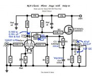
At these low signal levels, grid leak, AKA contact, bias is quite satisfactory. However, the 12AX7 is a wimp that can't fight it's way out of a wet paper bag. The "classic" passive EQ RCA design suffers from the same flaw. The tweaked RCA setup uses a FET buffer to provide some load driving capability. Note that the tweaked version uses grid leak bias in the 2nd gain block, which presents a light load to the EQ network. That light load improves bass extension.
Attachments
> two resistors and two capacitors required for RIAA.
The 2nd R is "not needed" if the amplifier just runs out of gain.
AND IF the NFB EQ parts are scaled so this happens about the right frequency.
> How do you all think it will sound?
Like a million basic "hi-fi"s 1957-1965. We thought it was good, but the gain inaccuracy and flabby sound would not be tolerated today.
I like simple, but this one is not worth building.
> second tube uses what is called "grid leak bias" which some consider to be a poor design option.
It arguably "works" here. Maybe. With large plate resistor it tends to lead to a Maximum Gain operating point, and we is desperate for gain here. It does not reliably give a Maximum Output operating point; however output level is reliably low (~~1V) and if the supply rail is sufficiently high then it will do. I do not think the estimated 105V B+ is "sufficiently high".
Eli's "Classic RCA" design is full passive RIAA and thus has reliable and consistent output impedance. I have not seen the MOSFET-buffed version before.
There are better designs than these. Three units of 12AU7 is not to be despised.
It was remarked that "12AX7 is a wimp". Not sure I agree. But I do think "all" single 12AX7 "RIAA preamps" fall short somehow.
Look at requirement. Pickup level is SMALL. We need a LOT of gain. How much?
We aim 1KHz gain around 50-150, call it 100.
We have 20dB boost at the lowest bass, so we need gain of 1,000 there.
If we use NFB to set gain/EQ, and hope for even 1dB accuracy, we need gain 10X in excess of the final gain. 10,000.
Yes, 12AX7 has Mu of 100, and 100*100 is 10,000. But we can't really get the gain of 12AX7 to 100. Not without more active devices to load, cascode, and buffer it. And when fully coddled, the tube doesn't sound "tube-like".
We can get gain of 50 easy, gain near 70 with extra high impedances. This still leaves us short of excess gain to enforce NFB accuracy. We then have to over-size or omit the resistor for the 50Hz corner, and let the <50Hz gain fall where it will.
So no-NFB does look interesting. Without NFB the overall gain will be at the mercy of the tube. Specifically your Left and Right will have the same EQ shape but may not match in level (have to lean your Balance control over).
Two stages of the medium-high Mu tubes will give gain of 1,000, and accurate stable R-C can RIAA this down to 100 near 1KHz and 10 at the top of the band. And even match the roll-off to infinity which is implied by RIAA and can't be readily done with non-inverting NFB.
These medium-high Mu tubes will give a somewhat high output impedance, slightly less than the tube plate impedance. Perhaps 25K? That can drive 3 foot cables but gets dubious for longer interconnects. (For the same reason, we do not extend the phono pickup wires more than 3 feet. While I like needle and Vol knob within my reach, some folks like other layouts.) One "advantage" of 12AX7 with NFB EQ is that the output impedance falls very low at the top of the audio band (and conversely, very high at the bass) and does drive small high-freq signals through cables OK.
So look at 3-triode plans? Maybe, but the possibilities for passive EQ between stages becomes confusing. You need to scale gain so the first stage's hiss dominates the rest despite EQ loss. You want the last stage run hot (lower gain) for good output drive.
*Maybe* the "best" of the one-12AX7 phonos is the Dynaco. (NOTE: should be another 750pF across the 68pF.) It was tweaked. Input stage runs at good current for lower hiss. Output stage good current for good drive. The extra trick is the 47K between cathodes. This is Positive feedback to increase open-loop gain. However we see this debatable trick is not enough to fully enforce the 50Hz corner: where we expect 1Meg we find 4.7Meg. Opinions vary-- it sure was better than nearly anything at the time, but a good 3-transistor preamp will whup it.
Attachments
Last edited:
At these low signal levels, grid leak, AKA contact, bias is quite satisfactory. However, the 12AX7 is a wimp that can't fight it's way out of a wet paper bag. The "classic" passive EQ RCA design suffers from the same flaw. The tweaked RCA setup uses a FET buffer to provide some load driving capability. Note that the tweaked version uses grid leak bias in the 2nd gain block, which presents a light load to the EQ network. That light load improves bass extension.
This looks interesting. I noticed that it looks like it needs 250v for B+ supply. I already have a 120v 93ma transformer on hand. Any way to utilize that with a circuit like this?
So look at 3-triode plans? Maybe, but the possibilities for passive EQ between stages becomes confusing. You need to scale gain so the first stage's hiss dominates the rest despite EQ loss. You want the last stage run hot (lower gain) for good output drive.
I agree and have heard some excellent 3 triode designs. However for my first build I would like to do the best 2 triode I can, biggest reason is I want to keep it as simple as possible and two I have a matched pair of 12ax7 and a small chassis on hand that I would like to utilize. I want to keep the investment in parts minimal in case things go south. Thanks for all the input. I am learning a lot already.
I agree and have heard some excellent 3 triode designs. However for my first build I would like to do the best 2 triode I can, biggest reason is I want to keep it as simple as possible and two I have a matched pair of 12ax7 and a small chassis on hand that I would like to utilize. I want to keep the investment in parts minimal in case things go south. Thanks for all the input. I am learning a lot already.
This looks interesting. I noticed that it looks like it needs 250v for B+ supply. I already have a 120v 93ma transformer on hand. Any way to utilize that with a circuit like this?
A reasonably good estimate of a rail's DCV is 1.3X the AC RMS value. Obviously 156 VDC will not do. However, a "full wave" voltage doubler gets you over 300 V.
A very solid 20+ mA. of B+ is available, which is quite sufficient. Add LR8 regulation (1 IC/channel) and all is well.Use an lr8 for hv regulation. The ripple is miniscule and using that device with just two small signal tubes, you shouldnt need to use a pass device like a horizontal output transistor.
This is the method that I used for my 6dj8 passive phono pre and it is dead silent. I would also suggest that you use dc for the heaters and do not put the pre in the same case as the power supply. Basically keep all sources of noise away from what will be a rather high gain amp.
Just my two cents worth.....
I agree and have heard some excellent 3 triode designs. However for my first build
I would like to do the best 2 triode I can
For a first build, I'd stay with the RCA passive circuit, with or without the follower output,
which could be added later. If properly designed, the RIAA is only slightly affected by the tubes.
The Dyna RIAA feedback circuit has LF problems, especially without the positive feedback.
Also the eq varies with the tube gain and condition.
Last edited:
For a first build, I'd stay with the RCA passive circuit, with or without the follower output,
which could be added later. If properly designed, the RIAA is only slightly affected by the tubes.
The Dyna RIAA feedback circuit has LF problems, especially without the positive feedback.
Also the eq varies with the tube gain and condition.
Ok if I omit the follower and build it as the original tube manual states, can I get away with lower B+ or do I still need a doubler to use the transformer I have on hand?
Ok if I omit the follower and build it as the original tube manual states, can I get away
with lower B+ or do I still need a doubler to use the transformer I have on hand?
With a FWB you could get 185VDC, since the primary is 110VAC, and the more usual
line voltage is 120VAC.
A voltage doubler would then give around 370VDC. If you use the doubler, you can use a
series power supply resistor large enough to drop the extra voltage, in the power
supply CRC filter after the rectifier. Choose a value to get 250VDC output. Make sure
that the power rating of the resistor is enough also.
Last edited:
A reasonably good estimate of a rail's DCV is 1.3X the AC RMS value. Obviously 156 VDC will not do. However, a "full wave" voltage doubler gets you over 300 V.
I have decided to build the modified RCA circuit with the FET follower. I have a couple of questions though. Some of the caps called out in blue on your schematic are very specific. I'm not quite sure what the "ECQ-P" and "GE" mean. Also the transformer I will be using for the psu (already have on hand) is this http://www.mouser.com/ProductDetail/Hammond-Manufacturing/262E6/?qs=3vio67wFuYoWdMjsoa8VRw==. Some suggestions have been made about using a voltage doubler and some regulation. Do you have a schematic on that?
Some suggestions have been made about using a voltage doubler and some regulation.
Do you have a schematic on that?
Regulation is not necessary if 400V capacitors are used, along with a suitable dropping resistor.
http://hyperphysics.phy-astr.gsu.edu/hbase/Electronic/ietron2/voldoub.gif
Last edited:
Regulation is not necessary if 400V capacitors are used, along with a suitable dropping resistor.
http://hyperphysics.phy-astr.gsu.edu/hbase/Electronic/ietron2/voldoub.gif
Thanks!
Thanks!
See the dyna preamp, just a quad cap and 3 resistors for the entire HV power supply.
Last edited:
- Status
- This old topic is closed. If you want to reopen this topic, contact a moderator using the "Report Post" button.
- Home
- Amplifiers
- Tubes / Valves
- Tube phono stage build