Hmm... 0.309% is what I'm getting using Ayumi's 6AU6 model and my 12AU7WA/6189 model. The quality of your model(s) has a great deal of influence on the accuracy of the THD results in LTspice or any other simulation software.
BTW, here's a Laplace with a correction factor for gain. I.E. 5mVin=5mVout.
Code:LAPLACE=(1+3.18e-3*s)*(1+7.5e-5*s)/((1+3.18e-4*s)*9.8759)
Thanks! This is really useful.. how did you come up with this correction factor?
I found it on the interweb somewhere and tweaked it a little.Thanks! This is really useful.. how did you come up with this correction factor?
")
Here's a drop-down IRIAA subckt and symbol I made for LTspice. It has both the 50kHz pole (3.18uS) and the standard RIAA curve.
Copy and paste this in your favorite text editor and save this as "invriaa_dd.asy" file and place it in your \lib\sym\<whatever> directory.
Code:
Version 4
SymbolType BLOCK
LINE Normal -64 0 -48 0
LINE Normal 64 0 48 0
LINE Normal 7 0 -7 0
LINE Normal 33 -32 7 0
LINE Normal -32 32 -7 0
RECTANGLE Normal 48 48 -48 -48
WINDOW 38 0 48 Top 2
WINDOW 0 0 -48 Bottom 2
SYMATTR SpiceModel RightClickMe
SYMATTR Prefix X
SYMATTR Description This symbol is for use with a subcircuit macromodel that you supply.
SYMATTR ModelFile INVRIAA_DD.txt
PIN -64 0 LEFT 22
PINATTR PinName I
PINATTR SpiceOrder 1
PIN 64 0 RIGHT 22
PINATTR PinName O
PINATTR SpiceOrder 2
Code:
.subckt RightClickMe IN OUT
.ends

.SUBCKT IRIAA IN OUT
+ PARAMS: tau_1=3180u tau_2=318u tau_3=75u CORR=9.8759 ; CORR=9.897
E1 OUT 0 LAPLACE {V(IN)}={(1+tau_1*S)*(1+tau_3*S)/((1+tau_2*S)*CORR)}
R1 OUT 0 1meg
.ENDS

.SUBCKT IRIAA_NEU IN OUT
+ PARAMS: tau_1=3180u tau_2=318u tau_3=75u tau_4=3.18u CORR=9.8759 ; CORR=9.897
E1 OUT 0 LAPLACE {V(IN)}={(1+tau_1*S)*(1+tau_3*S)/((1+tau_2*S)*(1+tau_4*S)*CORR)}
R1 OUT 0 1meg
.ENDSIf you are unable to save to those locations above because of ownership/permissions hassles in Windoze, save them in your working directory and point to it (include directive) on your schematic. When I used Win7, I took ownership of the LTC directory.
I think I will implement your cool little source. I also changed all of the permissions in win 7so I could add parts to the libraries.
Bought a new HP Elitebook for personal use with win 10 pro on it, will have it Monday. Will install LTSpice and report back on how difficult it is to reconfigure things.
Bought a new HP Elitebook for personal use with win 10 pro on it, will have it Monday. Will install LTSpice and report back on how difficult it is to reconfigure things.
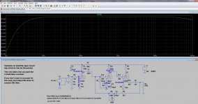
Here' s what I have been kinda working on...
Admittedly, its not as interesting as some of the other circuits posted, but it does the job for the time being and I am very happy with the sound stage. The RIAA appears to model much better than the original circuit, which of course was created in the days before spice. I have tested it using a test record, despite my inability to hear sounds at 15kHz and above.. the 50kHz pole probably makes no difference at all unless you happen to be the dog next door..
Its simulated for my Nagaoka MM cartridge, which has quite a significant internal resistance. Lower internal resistance is not a problem though.
I will probably replace the cathode follower with a ZVN0545A follower, which will likely change some component values... The RIAA caps are standard values Russian military silver mica and the coupling caps are polyprop film.
Ian
Attachments
Last edited:
Bought a new HP Elitebook for personal use with win 10 pro on it, will have it Monday. Will install LTSpice and report back on how difficult it is to reconfigure things.
I just had a battle with a Win10 PC that had write permissions blocked to the Program Files (x86) directory. The \Program Files (x86)\ directories are set as Read Only and can't be changed. I haven't had that problem on my PC, but I found out the hard way that it's not that easy with every installation.
I don't know if you'll be able to do it with your new PC, but when you go to install LTspice, I recommend *not* accepting the default program install location in C:\Program Files (x86)\LTC\...
Instead, try installing LTspice into C:\LTC\... if it will let you. That way you won't have the hassle I went through. I hope this helps.
--
Last edited:
I found it on the interweb somewhere and tweaked it a little.
Here's a drop-down IRIAA subckt and symbol I made for LTspice. It has both the 50kHz pole (3.18uS) and the standard RIAA curve.
Copy and paste this in your favorite text editor and save this as "invriaa_dd.asy" file and place it in your \lib\sym\<whatever> directory....
That's fantastic! Thank you for sharing that. Just awesome.
--
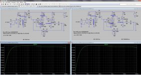
I got a chance to run a little comparison. I've attached two screenshots of a simple 12AX7 phono preamp circuit sim, one with a passive inverse RIAA network and the other with this cool new Laplace inverse RIAA. They don't totally agree on the bass response, but they're very close to each other. Is the Laplace version more accurate?
--
--
Attachments
The accuracy of a passive RC RIAA network depends on the values given and the output impedance of your voltage source. A laplace on the other hand, is a mathematical source.I got a chance to run a little comparison. I've attached two screenshots of a simple 12AX7 phono preamp circuit sim, one with a passive inverse RIAA network and the other with this cool new Laplace inverse RIAA. They don't totally agree on the bass response, but they're very close to each other. Is the Laplace version more accurate?
--
Here's a passive RC network that takes a 600 ohm (parasitic series resistance) source impedance.
I detect very little difference from it and the laplace on a SE input preamp, except at the high end of the freq spectrum (using the passive) where input capacitance of the circuit under sim comes into play.
When using either passive or laplace set your AC Amplitude=1 for the small signal AC analysis. With AC Amplitude=1 using the laplace you will read your actual circuit gain. With the passive you will read actual circuit gain minus the signal loss of the RC network. Of course you probably knew that.

Last edited:
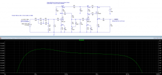
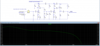
After re-reading section 10.1.2 of Merlin Blencowe's very good book, I have decided it best to do away with the 50kHz pole.
Here are my current iterations on the "ear834p" type circuit with the 3 RIAA cut-off frequencies. Frequency response is very similar with the ZVN0545A MOSFET follower.
Here are my current iterations on the "ear834p" type circuit with the 3 RIAA cut-off frequencies. Frequency response is very similar with the ZVN0545A MOSFET follower.
Attachments
Here are my current iterations on the "ear834p" type circuit with the 3 RIAA cut-off frequencies. .
!!!

After all the technical discussion and digressions that have happened here, I'm happy though somewhat abashed to say that I've opted for the VTA PH16. It has all the attributes I was looking for -- no feedback, near-dual-mono power supplies, DC heaters, buffer stage, ca. 45db of gain, and excellent performance in a low parts-count, modestly priced package. Roy Mottram has been incredibly attentive to questions via email and shipping was fast.
I'm planning to put the power supply and RIAA section in separate enclosures. I've also ordered a Denon DL-301 mkii MC cartridge and will need to select step up transformers. Since I plan for this to be a dedicated MC system, I'll build them directly into the RIAA chassis for direct connections and a simple grounding scheme.
Thanks again for all of the information that has been posted here. I've learned a lot from this thread and hope that it will be useful to other builders contemplating phono stages.
I'm planning to put the power supply and RIAA section in separate enclosures. I've also ordered a Denon DL-301 mkii MC cartridge and will need to select step up transformers. Since I plan for this to be a dedicated MC system, I'll build them directly into the RIAA chassis for direct connections and a simple grounding scheme.
The exchange rate between USD and UKP is favorable, at this time. You can take advantage of that fact to order Sowter 9570 cartridge transformers. The 19 mM. mounting centers are just fine at 0.75 inches (more than close enough for government work) and non-magnetic stainless steel M3 screws are easy enough to source. I bought some years ago from McMaster/Carr.
Thanks Eli. I'm considering the 9570. The DL-301ii (0.4mV, 33 ohm) would seem to require a turns ratio of 1:12.5 to bring the cart's output to 5mv (0.4 * 12.5 = 5). Is that correct?
If so, then the Sowter 9580 seems ideal, although the product overview page lists it as being for carts with an internal impedance of greater than 40, so I'm not sure how well it would work. I've emailed Sowter about it but not heard back.
I've also read a number of reviews that claim Sowter SUTs "shrink" or reduce the soundstage compared to other ones like Lundahl. The three-dimensionality of the soundstage is actually really important to me (and one reason I chose the PH16), so if anyone has experience with SUTs and can chime in with suggestions, I'd appreciate it.
Just so I'm clear, are you saying there needs to be a little head room for peaks to be passed on to the phono stage without clipping?
Not so much a question of headroom as not producing too "tall" an O/P voltage for whatever follows the phono preamp. Many a LP will have passages that cause the cart. to generate more than 0.4 mV.
FWIW, passive EQ designs are more overload resistant than active EQ designs.
- Status
- This old topic is closed. If you want to reopen this topic, contact a moderator using the "Report Post" button.
- Home
- Amplifiers
- Tubes / Valves
- Tube Phono Preamps