Seems the trade-off is between high rp in the first stage 12AX7 causing RIAA inaccuracies from getting loaded down by the second stage's grid leak resistor (usually 1M)
--
Here's what I'm doing for this calculation (with the help of Excel):
Rs'' is the series resistor value calculated with the RIAA constants, Rs' is an intermediate variable, and Rs is the actual resistor value needed. Rg is the following stage's grid leak. Zout is the preceding stage's output impedance.
Rs'' = Rs' || Rg
Rs' = Rs + Zout
or Rs = (Rs'' x Rg)/(Rg - Rs'') - Zout
Hopefully I'm calculating this correctly. Higher Rg means less gain reduction from the voltage divider between Rs and Rg but also greater chance of noise. Generally lower cap values in the network mean larger calculated resistor values, making any miscalculation of Zout (or drift over time) less of an issue.
Another version of classic RCA tube phono circuit.
The PCB is sized to fit in Dynaco PAS but can be used to make a stand alone
phono preamp.
Classic Valve Design - Dynaco Clone and Original Design Boards
The PCB is sized to fit in Dynaco PAS but can be used to make a stand alone
phono preamp.
Classic Valve Design - Dynaco Clone and Original Design Boards
Anytime!
I've learned an awful lot in the last couple of years by reading Morgan Jones' "Valve Amplifiers" and more recently, Merlin Blencowe's "Designing High Fidelity Tube Preamps". Both of those books have excellent chapters on the properties of the passive parts we use in tube circuits. One of the things I've read in both books is that a little noise reduction may be obtained by using resistors with higher dissipation ratings than absolutely necessary. Having the resistors run cool is also a good idea. I'd say choosing a resistor with a dissipation rating of 3X to 5X the in-circuit dissipation will give you a nicely cool-running resistor.
--
Tu ingles me parece perfecto, Felipe")
Wow your Spanish is really perfect
Rongon;"There's 140V dropped across R8, so
140V * 0.015A = 2.1 watts, so a 5W part should be OK for R8."
Nice, but R8 is 7k5. Current 140/7500=18.67mA ! not 15mA
The current in the triode has to be bigger than that in R8 since the screen current also goes through the triode.
Here the opposite is shown, the numbers don't add up.
Also the voltage drop on the led isn't right if you look at the tube data, more 1.9V not 1.65V.
I think Mr Bokarev has to go back to the drawingboard.
Mona
Good catch!
I was going by the voltages in the circuit diagram, which I assumed were all checked and correct. Hah! You know what they say... When you assume, you...
Since the screen current's there too, and 140V gets dropped across 7k5, making 140V at 18.67mA, then:
140V * 0.019A = 2.66W
Therefore, a 5W rated resistor would be just barely adequate. 7W or 10W would be the better choice.
Thanks Mona.
--
Last edited:
Como un ciego y un sordo
Yes that's the feeling when I read technical words...
Here is the tweaked RCA Classic phonostage that Eli, Buzz and others have worked on. The power supply will follow if you're interested. (I thought Merlin had just posted it, but it's gone at the moment.)The range in values shown is intended to keep a key RC product constant.
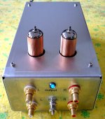
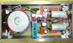
This is my version in a Hammond natural alu case.
Attachments
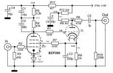
Looking at that Bokarev pre, I was thinking why not use a triode/pentode tube ? All in one !
A problem is that most have the triode anode and the pentode control grid side by side, not very comfortable (oscillations)
But the ECF200 is ok, has 10pin noval like base.Only drawback, the triode is not very powerfull.Results in a somewhat higher output impedance.
Just an idea
Mona
A problem is that most have the triode anode and the pentode control grid side by side, not very comfortable (oscillations)
But the ECF200 is ok, has 10pin noval like base.Only drawback, the triode is not very powerfull.Results in a somewhat higher output impedance.
Just an idea
Mona
Attachments
You've got an 8k2 plate load resistor on the 12AU7, which is about 1:1 with the plate resistance of 12AU7. Distortion would be very high, wouldn't it?
Also, someone mentioned earlier that the Bokarev EQ uses the inductance of the cartridge to set the RIAA correction. That means the preamp will sound different if you switch from a relatively high inductance MM like a Shure to a lower inductance HOMC like Denon DL110. That could be a problem. Has anyone come up with a way to model that?
Perhaps the second stage triode should be something with low ra, like a 6N6P. That way you could get reasonable linearity and a lower output impedance.
--
Last edited:
For what it's worth...
I just simulated the Bokarev circuit (original but using an E180F for the input pentode and 6N6P for the output triode). I get a 'saddleback' shaped frequency response into 100k load:
-0.5dB at 20Hz
+1dB at 65Hz
0dB at 1kHz
+2.5dB at 10kHz
+2dB at 20kHz.
It also looks like the THD is rather high at 1.5V RMS output (0.1%), but we know LTspice doesn't predict distortion accurately. However, this circuit makes 2 to 5 times the distortion of other RIAA circuits I've been simulating.
--
Last edited:
- Status
- This old topic is closed. If you want to reopen this topic, contact a moderator using the "Report Post" button.
- Home
- Amplifiers
- Tubes / Valves
- Tube Phono Preamps