coupling caps ...
Hello dikarner,
If you have trouble with coupling caps,
just remove them by tubes.
"culture shock"
Kind regards,
Darius
Hello dikarner,
Originally #40 posted by dikarner
Over the weekend, I played around quite much with the phonostage. First I moved coupling-cap ...
If you have trouble with coupling caps,
just remove them by tubes.
"culture shock"
Kind regards,
Darius
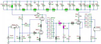
After extensive testing/changing and rerouting of the Anode powerconnections between (R17&R1 / R10&R2) and making the groundconnections as much as possible in a star-array I am VERY happy with the result. The "now final" circuit is below.
The capacitors are now mainly roederstein KP1835 and some small WIMAs to finetune the values, several resistors (R2 (which can also be bypassed without problems), R10 & R11) have been replaced with carbon composite types NOS.
@oshifis:
intrigued by your post about VARs, I'll get a quote from www.texascomponents.com.
Questions is: Which ones best to replace? Where does it matter most?
I am guessing R2, R11 and R8 ?
What about R1, R9 and R10?
What about the others (connected to grid of 6922_1; shunt at the output; cathode?)
Thanks.
Dieter
Attachments
That's pretty close to the same value that Joe Curcio used in his ECC88 cascode diff amp for the ST-70 mod. Seemed to work pretty well. You need something large there to set the pole of the RC filter low enough. If there's any grid leakage, the cathode voltage will rise to compensate anyway.
I see, thanks. That raises the question of how low you want that pole. Just bypassing the 150k with the 100n would put it at 10, and increasing the cap by a factor of 10 wouldn't be a big deal. Or using a 300k resistor instead of 3meg would put the pole at 2.5. Do you really want a phono amp much lower anyway?
Sheldon
Sheldon
@sheldon
being an ignorant in electronics - see original post - I have to ask for further explanation on your grid-bias comments or to send me a link or keywords to search with....
exactly this part of the circuit is the one I understand the least, actually not at all and I would really like to udnerstand what's going on there.
Thx.
Sheldon, I'd want it low, with a nice big cap there, too. This is a noise injection point.
Kill that noise! Kill it dead!
(disclaimer: I haven't biased the top of a cascode this way in low level circuits, so there may be problems I'm unaware of. In my former preamp, the upper grid of the cascode was fed from a very low noise reference, an LM399)
Kill that noise! Kill it dead!
(disclaimer: I haven't biased the top of a cascode this way in low level circuits, so there may be problems I'm unaware of. In my former preamp, the upper grid of the cascode was fed from a very low noise reference, an LM399)
R7 may not be needed. I've seen resistors used in that position to prevent oscillation, so perhaps that was the original function?
R6 adds noise, indeed, but this is a MM preamp, so compared with the equivalent noise resistance of the cartridge... say, wasn't that YOUR argument?
R6 adds noise, indeed, but this is a MM preamp, so compared with the equivalent noise resistance of the cartridge... say, wasn't that YOUR argument?
dikarner said:being an ignorant in electronics - see original post - I have to ask for further explanation on your grid-bias comments or to send me a link or keywords to search with....
exactly this part of the circuit is the one I understand the least, actually not at all and I would really like to udnerstand what's going on there.
Thx.
Not sure which part you are asking about, the cascode itself, or the discussion about the decoupling cap for the upper grid reference. Here's a description of the cascode: http://www.tubecad.com/march99/page2.html
It's basically like making a triode act like a pentode by isolating the plate of the top triode from voltage changes at the bottom triodes cathode. It has high gain like a pentode, but low noise, and like a pentode it has very low input capacitance, all of which make it useful as an input stage for a high gain amplifier. As Darius (Oldeurope) pointed out to me, it also has the distortion characteristics of a pentode.
The voltage divider that goes to the grid of the top triode, sets the voltage at the bottom triodes plate. You pick that voltage for the bottom triode, as you would for a normal triode amplifier. The cap from the top grid to ground, or usually across the bottom resistor of the divider is just to remove any remaining power supply noise from that point. But you must have a DC path to ground for the grid. In your schematic, it goes through a 3.3 meg resistor, which is pretty high. My concern is that it could change your operating point. May not be a big deal in practice, but you'd like both channels to be as similar as possible.
SY mentioned that that grid can be a noise injection point, so use a big cap and big resistor to reduce it as much as possible. I think you can get by with a smaller grid lead resistor, but if it works and your channel to channel operating values for the bottom triodes plate are within 5 or 10V don't sweat it.
Ah, but here's where it gets interesting, and you can ignore all of the following if it's too much.
Because your top triode is sitting on another triode, it's as if you have a very large unbypassed cathode resistor for the top triode. That means the internal resistance of the top triode will be very high. The consequence of that is that any noise in the B+ will pretty much show up 100% in the output of that first stage. In other words, its PSRR is almost zero. But you can cancel this by actually injecting some of the power supply noise at that grid. Using the calculations from the citation above, it looks like you would need to inject about 20% of the PS noise. If you had no cap at all in that circuit, with your divider values you'd inject 150k/[150k=470k] = 0.21. By happy coincidence, your amp might be quieter if you left out that cap entirely!
Back to you SY
Sheldon
SY said:I'm leery of the stability of noise cancellation schemes.
Yes, something to consider. I had difficulty getting Steve Bench's filament noise cancellation scheme to work as well as I wanted for an 801. But that involves getting all the phases correct for the various harmonics. In this case, phase is not an issue, and stability should be good as the only variable is the u of the tube, which is supposed to be stable. I use a pot as JB suggests for his circuit, so I can fine tune if I change tubes.
Sheldon
thanks for the elaborate explanation, Sheldon. It will take me a while but I'll try to fully understand.
concerning power-supply noise: how does it sound? like "white noise" or like 50/60hz hum?
when turning up the volume, of the first I hear plenty, of the latter almost none.
I removed the cap and the Hum increased significantly, the "white" noise stayed pretty much the same, could not hear a difference. Actually I tried only one channel so I could easily make out the difference.
dikarner said:thanks for the elaborate explanation, Sheldon. It will take me a while but I'll try to fully understand.
concerning power-supply noise: how does it sound? like "white noise" or like 50/60hz hum?
when turning up the volume, of the first I hear plenty, of the latter almost none.
I will remove the cap and listen if the noise level changes.
I will also remove R7 and see how the voltages change and how it sounds different.
The predominate power supply noise will the double the mains frequency. In your case, I'm assuming 100Hz. White noise, or hiss is due to random noise generated by the tubes and resistors. High levels of hiss can be due to oscillation, but you are probably ok there.
Your power supply should be pretty quiet, so you may not hear a difference by disconnecting one end of the cap. Curious to see.
Shorting or removing R7 shouldn't change much.
Sheldon
Removing the cap added quite some hum/PS noise at full volume. (I edited while you replied).
Removing R7 actually brought the PS noise (with the cap) from very little to hardly perceptible no difference with the other noise level. No hiss either.
At full volume I now hear a lot of the tube/resistor noise and no PS noise.
Will quieter resistors (foils) remove the noise level or not because the tubes alone are noisy "enough" for this not to make a difference?
Removing R7 actually brought the PS noise (with the cap) from very little to hardly perceptible
no difference with the other noise level. No hiss either.At full volume I now hear a lot of the tube/resistor noise and no PS noise.
Will quieter resistors (foils) remove the noise level or not because the tubes alone are noisy "enough" for this not to make a difference?
dikarner said:Removing the cap added quite some hum/PS noise at full volume. (I edited while you replied).
Removing R7 actually brought the PS noise (with the cap) from very little to hardly perceptible
At full volume I now hear a lot of the tube/resistor noise and no PS noise.
Will quieter resistors (foils) remove the noise level or not because the tubes alone are noisy "enough" for this not to make a difference?
Good work. Nice to get actual data. The biggest contributor of resistor noise, by far, would be the cathode resistor R6. You could try a low noise resistor there. You could also look for a low noise resistor for the 20k plate resistor, but that will make much less difference.
Sheldon
For R6 as Vishay Z-Foil naked texas-components quotes 11.44$ - that is affordable.
What about the cathode resistor in the second stage?
What about the resitors in the RIAA and the grid-stoppers?
For R8 (95k) and R10 (400k) The prices are prohibitive.
here's the full quote:
TX2352 (low noise) with 0,05% tolerance
2pc 95k TX2352 95K000 0.05% $16.31 each
2pc 10.33k TX2352 10K300 0.05% $8.16 each
4pc 250k TX2352 250K00 0.05% $44.86 each
4pc 100R TX2352 100R00 0.05% $8.16 each
4pc 140R TX2352 140R00 0.05% $8.16 each
4pc 400R TX2352 400R00 0.05% $8.16 each
To ship 2 weeks or sooner after order placement.
TX2575 (no noise ) with 0,01% tolerance
2pc 95k TX2575 95K000 0.01% $22.87 each
2pc 10.33k TX2575 10K330 0.01% $11.44 each
4pc 100R TX2575 100R00 0.01% $11.44 each
4pc 140R TX2575 140R00 0.01% $11.44 each
4pc 400R TX2575 400R00 0.01% $11.44 each
To ship 2 weeks or sooner after order placement.
What about the cathode resistor in the second stage?
What about the resitors in the RIAA and the grid-stoppers?
For R8 (95k) and R10 (400k) The prices are prohibitive.
here's the full quote:
TX2352 (low noise) with 0,05% tolerance
2pc 95k TX2352 95K000 0.05% $16.31 each
2pc 10.33k TX2352 10K300 0.05% $8.16 each
4pc 250k TX2352 250K00 0.05% $44.86 each
4pc 100R TX2352 100R00 0.05% $8.16 each
4pc 140R TX2352 140R00 0.05% $8.16 each
4pc 400R TX2352 400R00 0.05% $8.16 each
To ship 2 weeks or sooner after order placement.
TX2575 (no noise
) with 0,01% tolerance2pc 95k TX2575 95K000 0.01% $22.87 each
2pc 10.33k TX2575 10K330 0.01% $11.44 each
4pc 100R TX2575 100R00 0.01% $11.44 each
4pc 140R TX2575 140R00 0.01% $11.44 each
4pc 400R TX2575 400R00 0.01% $11.44 each
To ship 2 weeks or sooner after order placement.
dikarner said:For R6 as Vishay Z-Foil naked texas-components quotes 11.44$ - that is affordable.
What about the cathode resistor in the second stage?
What about the resitors in the RIAA and the grid-stoppers?
I don't have a lot of experience, but I've not heard much difference in noise changing from good quality metal films to other types. Wire wounds are the lowest. The foil may be on the same order, but I've never tried those. Try R6 if it's not too expensive. If you hear no difference, you won't hear the others. You might be able to detect a difference with the second cathode resistor, but it will be less than the first. You could try bypassing it as a test. Maybe a good wirewound for the 20k, but I couldn't tell any difference there, in my pre, between a wire wound and a carbon film. Bigger resistors (higher wattage) will make less noise than smaller ones. Other than that, I doubt it's worth the effort. You may see bigger differences in noise with individual tubes.
Also, compare the preamp noise to record surface noise, by listening to the lead-in or runout grooves of a few records. If that noise is much louder than your preamp noise, then you are chasing diminishing returns.
Sheldon
This sounds very reasonable to me. The surface noise actully is significantly louder...so noisewise not much might be to gain.
I was actually thinking about battery-biasing te tubes to see if the noise changes without the cathode Rs.
Right now the Voltage at the cathodes is around 1.6 so a simple AAA should do the trick, right?
Then I'm also waiting for oshifis to return and share his insights on the sonical improvements since using these resistors.
You're dead on again about the tubes making the most difference. I rolled a few last night (E280F, D3a, E282F, E180F, E810F - they all fit ) in the second stage. And besides sonic differences also the noise levels are quite different.
In the first stage I already have CCa from Siemsn 1962 and it does not get much better then that.
I was actually thinking about battery-biasing te tubes to see if the noise changes without the cathode Rs.
Right now the Voltage at the cathodes is around 1.6 so a simple AAA should do the trick, right?
Then I'm also waiting for oshifis to return and share his insights on the sonical improvements since using these resistors.
You're dead on again about the tubes making the most difference. I rolled a few last night (E280F, D3a, E282F, E180F, E810F - they all fit
) in the second stage. And besides sonic differences also the noise levels are quite different.In the first stage I already have CCa from Siemsn 1962 and it does not get much better then that.
- Status
- This old topic is closed. If you want to reopen this topic, contact a moderator using the "Report Post" button.
- Home
- Amplifiers
- Tubes / Valves
- Tube phono amp repair/redesign help wanted