This stage drives the insert which will be plugged into external FX and EQ units. These usually have a nominal 10K input impedance.
Ok this can be a problem. The solution could be to use E88CC as cathode follower.
It will reduce distortion but unfortunately the distortion in a normal common cathode amplifier starts quite high, even when bootstrapped. This means that even after NFB the distortion is very similar to that of he 6CG7 mu follower. It is OK provided you don't need any serious drive capability. It is certainly measurable.
The distortion of the common cathode stage is very low, because it has high impedance load. The bootstrapping can push up the load to 10M.
It does reduce noise of the tone control stage.Negative feedback does NOT reduce noise.
I said the passive EQ really needs a gain make up amplifier after it - equal to the passive EQ loss. Thus the overall gain is unity just as for the NFB case. 2V in gives 2V out.
Gain stage before the passive Eq means more distortion. Gain stage after the passive means more noise. Which is better?
Sajti
Ok this can be a problem. The solution could be to use E88CC as cathode follower.
Yes, all that is needed is sufficient standing current.
No matter how high the effective anode load, the distortion will only reduce to the intrinsic distortion of the tube. Unfortunately the intrinsic distortion of the 12AX7 is rather high.The distortion of the common cathode stage is very low, because it has high impedance load. The bootstrapping can push up the load to 10M.
It reduces the noise added by the tone control stage by the amount the gain is reduced. The output signal to noise ratio is no better than the input signal to noise ratio.It does reduce noise of the tone control stage.
Gain stage before the passive Eq means more distortion. Gain stage after the passive means more noise. Which is better?
Sajti
Gain stage after passive EQ is better. Noise at this stage is not normally a limiting factor.
Cheers
Ian
Originally Posted by ruffrecords View Post
Do you think that eliminating the second stage of the first Aikido the second Aikido can reduce the noise in the same manner as with two Aikido sections?
In the second Aikido, there is a double reason: in part, for the above reported consideration and, in part, for the necessity of driving a load not simple (tone control + mixer bus … with 1 mt of cable). I think that in this case the second section cannot be eliminated.
Furthermore, I cannot eliminate the first Aikido stage because I must have two amplifier stages for the mic input (2 mV). On the contrary, with a single preamplifier stage the mic signal will be increased of only 19 dB (gain=6.45x14/10=9).
However, reflecting on your suggestion… I could consider a combination of ECC85/6DJ8 (with a gain of 30) for both Aikido stages. In this case, I could consider a ECC85/6DJ8 as input stage (the “line” input entering after the transformer) and a second ECC85/6DJ8 after the tone control. In this case, the gain becames 6.45x30/10x30=585 (55 dB)… enough for both signals (mic e line).
I have already tested this combination and the frequency range is very wide (5Hz-75KHz; +/- 1 dB). What do you think?
You are right, it is wrong … effectively in the schematic you refer the orange lines are taken after the fader but that is not the “general schematic”. This is reported here Mixer - general scheatic | Agorà.OK, I understand. However, my question was about the monitor (headphone) sends rather than the insert (send/return). On the 'general schematic these (orange lines) are taken after the fader. Is this correct?
Ok. Thank you for the elucidation. Now I’ve clearly understood and agree with you. I’ll include the resistor in the next schematic.The gain of the transformer and the first Aikido stage is about 39dB. So, if the maximum output from the Aikido before serious distortion is 20V rms (+26dBV) then the highest input signal you can handle is 26 - 39 dBV =-13dBV or about 220mV. So the question becomes how likely is a microphone signal level of 220mV? The answer, with close miked drum kits and guitar cabs, is very likely so I would definitely recommend including a switched 20dB pad. The usual place for this is right next to the transformer primary.
I know that the second section of the Aikido is a unity gain buffer … however, I included it in order to strongly reduce the noise from the power supply (through the R-C net connected with the grid of the bottom valve of the second section). This choice was dictated by the need of minimizing the noise in the first stages of amplification.The first tube in the Aikido provides all the gain. The second stage is a unity gain buffer/driver. For the fist Aikido stage you do not need the buffer stage (the right hand ECC88) so you can delete it. You can just take the output from the cathode of the top tube of the first stage. The same can be done with the second Aikido.
Do you think that eliminating the second stage of the first Aikido the second Aikido can reduce the noise in the same manner as with two Aikido sections?
In the second Aikido, there is a double reason: in part, for the above reported consideration and, in part, for the necessity of driving a load not simple (tone control + mixer bus … with 1 mt of cable). I think that in this case the second section cannot be eliminated.
What do you think about the scaling up of 5 (for the tone control)?Yes the loss is the same. The reason for doing it is to reduce the load on the stage that drives the tone stack
In this case, I have to introduce 10 further Aikido stages (each including both sections, preamplifier and buffer stage), so… 10 tubes. Utilizing a summing amplifier with a 10x gain, I have to utilize only 4 Aikido stages (1 for each of the four sections … voice, bass, right, and left).I think it would be better to make up the gain of the tone stack before mixing in order to avoid noise problems so I would suggest placing an SRPP (effectively the first stage of the Aikido) after the EQ to bring the level back up to a nominal 2V or so.
Furthermore, I cannot eliminate the first Aikido stage because I must have two amplifier stages for the mic input (2 mV). On the contrary, with a single preamplifier stage the mic signal will be increased of only 19 dB (gain=6.45x14/10=9).
However, reflecting on your suggestion… I could consider a combination of ECC85/6DJ8 (with a gain of 30) for both Aikido stages. In this case, I could consider a ECC85/6DJ8 as input stage (the “line” input entering after the transformer) and a second ECC85/6DJ8 after the tone control. In this case, the gain becames 6.45x30/10x30=585 (55 dB)… enough for both signals (mic e line).
I have already tested this combination and the frequency range is very wide (5Hz-75KHz; +/- 1 dB). What do you think?
Last edited:
Ian, I reflected on what I proposed yesterday (one ECC85/6DJ8 Aikido stage at input and another ECC85/6DJ8 Aikido stage after the tone control).I think it would be better to make up the gain of the tone stack before mixing in order to avoid noise problems so I would suggest placing an SRPP (effectively the first stage of the Aikido) after the EQ to bring the level back up to a nominal 2V or so.
With this configuration we have a problem. After the first ECC85/6DJ8 the mic signal is 390 mV while the line signal is 3.000 mV. This discrepancy induces us to utilize a resistor drop on the "line" circuit to achieve a 20 dB reduction of the signal (to obtain 300 mV at the output of the first stage)... and this does not seem a good operation.
Then ... I do not know how much of the signal we can loss into the balance control...and having 1.1 VRMS at the output of the second ECC85/6DJ8 stage troubles me a little.
So, returning to the original configuration ... why you do not like that? Which problems could it hide?
Last edited:
http://www.bestsellers-store.com/audiospeaker/images/stories/Valve/tube tone.png
This is very simple. But the quality can be better with the other half of the tube
Sajti
Effectively, the schematic is simple but it think that it does not reduce the number of the stages. In fact, we in any case need of two input stages (one for mic and another for line), because the two input have very different signal level (2 and 100 or more mV)... and the circuit you propose cannot be interposed between them. So, in any case we’d need of a further tone stack stage.http://www.bestsellers-store.com/aud...ube tone.png
This is very simple. But the quality can be better with the other half of the tube
we in any case need of two input stages (one for mic and another for line),
Would not a simple ~40db pad in front of the mic pre input transformer do the job (for a single input stage?)
4P3T switch - 0, -20db, -40db
I know that the second section of the Aikido is a unity gain buffer … however, I included it in order to strongly reduce the noise from the power supply (through the R-C net connected with the grid of the bottom valve of the second section). This choice was dictated by the need of minimizing the noise in the first stages of amplification.
Do you think that eliminating the second stage of the first Aikido the second Aikido can reduce the noise in the same manner as with two Aikido sections?
The first stage of the Aikido is an SRPP. It has a gain of mu/2 and a low output impedance.
The second stage also provides a low output impedance and also helps improve the power supply rejection ratio (PSRR). The top cathode follower of the second stage already provides a PSRR of mu times so the Aikido effect is on top of this. The real question is just how dirty is your HT supply? In my experience it is quite possible to build an HT supply that is really clean and I have never needed the Aikido to clean it up further.
In my designs I use mu follower stages using the 6CG7 which produce a gain of 26dB a low output impedance and they have a PSRR of over 20dB. I have built several microphone pre-amplifiers using two of these and a Sowter 1:10 input transformer giving an overall gain of 70dB. HT noise has not been a problem. Heater hum has been a problem and the solution is dc heaters.
In the second Aikido, there is a double reason: in part, for the above reported consideration and, in part, for the necessity of driving a load not simple (tone control + mixer bus … with 1 mt of cable). I think that in this case the second section cannot be eliminated.
As I noted above, the first stage of the Aikido is an SRPP. It is quite capable of driving the tone control stack + mixer bus with 1mt of cable.
What do you think about the scaling up of 5 (for the tone control)?
I think that is OK.
Cheers
Ian
Hi Antonio,
I have drawn a block diagram, Neve style, of what I believe you want, showing the signal level at each stage. If this is close to what you need then the only remaining question is what is in each gain block. Using the SRPP only part of the Aikido and regular cathode followers for the unity gain parts I make it a total of 47 tubes.
Cheers
Ian
http://www.ianbell.ukfsn.org/data/PAmixer.pdf
I find that in the design process I must often leave "attachments" behind to get a better design; i.e. something that I thought was a great idea, maybe even the original design idea, has to be abandoned because it ends up compromising the quality of the design.
In this case, I see 2 such "attachments". First, Aikido amplifiers. The Aikido is a great circuit, but insisting on using it as a building block everywhere doesn't serve all the design goals. It's what I call a "local optimization" for PSRR that actually burdens the rest of the design to make allowances. You don't always need "X" PSRR at the expense of gain and thermal noise for example. All amplifier blocks don't need the same output impedance... etc.
The second "attachment" is trying to get by with one amplifier for both line input and EQ makeup gain. Ian's approach is so much better with only one more amplifier per channel. The makeup gain amp belongs after the EQ for many already-stated reasons. In this way, only the line amp needs to have low impedance drive capability for the EQ net and the insert, and the EQ makeup amp gain can be fixed such that the level doesn't change when you insert a unity gain processor.
Cheers!
Michael
Last edited:
Ian,
I and my son thank you very much for your precious support. We greatly appreciated it.
We carefully analyzed your proposal and found it very interesting (and, obviously, more professional than our schematic).
We have only few questions to submit. Specifically,
1) Why did you insert a PAD between EQ and the following gain stage?
2) Are both “CF” the “o” (pre and post fader) two cathode follower stages of a single tube?
3) About the mixer bus of “Bass-Vocal-Right-Left” … What happens to a signal travelling into a line-bus if other unused channels connect that bus to ground?
4) Which of the reported gain stages are Aikido (with both preamplifier and CF sections), simple SRPP, or CF ?
Last edited:
Ian,
I and my son thank you very much for your precious support. We greatly appreciated it.
We carefully analyzed your proposal and found it very interesting (and, obviously, more professional than our schematic).
I am happy to be able to help.
We have only few questions to submit. Specifically,
1) Why did you insert a PAD between EQ and the following gain stage?
To ensure the overall EQ gain is unity with the controls set flat. The EQ insertion loss will not be exactly 20dB and the following amplifier will probably have more than 20dB gain so the pad is there so that insertion loss plus pad equals gain make up.
2) Are both “CF” the “o” (pre and post fader) two cathode follower stages of a single tube?
They are both assumed to be cathode followers. Sometimes I write CF and sometimes 0 (for 0dB gain). I had assumed they were in the same tube.
3) About the mixer bus of “Bass-Vocal-Right-Left” … What happens to a signal travelling into a line-bus if other unused channels connect that bus to ground?
As this is a block diagram I have not shown the bus resistors. So each connection from the channel to the bus is assumed to be via a bus mix resistor. The design assumes passive mixing so unused connections to the bus must be grounded to maintain the proper bus impedance.
4) Which of the reported gain stages are Aikido (with both preamplifier and CF sections), simple SRPP, or CF ?
That is something you can choose. However, in calculating the total number of tubes I have assumed all the gain stages are SRPP and all the CFs are single tube CFs
Cheers
Ian
Ian,
we reflected about your suggested schematic and elaborated it. The main elaborated (and, consequently, modified) points were:
1) We substituted the first two Aikido stages (1 and 2 of your schematic … see figure 1) with two SRPP (practically, we simple eliminated the second section of the previous Aikido and added a capacitor of 1uF followed by a 1MR to ground).
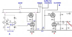
2) Stage 3 and 4 of your schematic were substituted with a modified Aikido stage (see figure 1 and 2).
3) A, B, C, D, E in your schematic have been considered and included into our new schematic (see figure 2).
With this approach, we utilize only 4 tubes for channel (as in our previous schematic).
Please take a look at the new schematic and tell us what you think.
Specific questions are:
1) Do the first two stages (now SRPP) followed by the Aikido (at the 3rd-4rd stage) have the some PSRR of the primary two AIKIDO stages (in our previous schematic)?
2) Is it possible to directly connect buffer for monitors and vu-meter to the points reported into the schematic (…without a capacitor)?
3) Are the values proposed for some components (in blue characters followed by a question mark) correct?
4) Objectively … How do you consider our new approach (and in general the whole project)?
we reflected about your suggested schematic and elaborated it. The main elaborated (and, consequently, modified) points were:
1) We substituted the first two Aikido stages (1 and 2 of your schematic … see figure 1) with two SRPP (practically, we simple eliminated the second section of the previous Aikido and added a capacitor of 1uF followed by a 1MR to ground).
2) Stage 3 and 4 of your schematic were substituted with a modified Aikido stage (see figure 1 and 2).
3) A, B, C, D, E in your schematic have been considered and included into our new schematic (see figure 2).
With this approach, we utilize only 4 tubes for channel (as in our previous schematic).
Please take a look at the new schematic and tell us what you think.
Specific questions are:
1) Do the first two stages (now SRPP) followed by the Aikido (at the 3rd-4rd stage) have the some PSRR of the primary two AIKIDO stages (in our previous schematic)?
2) Is it possible to directly connect buffer for monitors and vu-meter to the points reported into the schematic (…without a capacitor)?
3) Are the values proposed for some components (in blue characters followed by a question mark) correct?
4) Objectively … How do you consider our new approach (and in general the whole project)?
Attachments
Last edited:
Ian,
we reflected about your suggested schematic and elaborated it.
Please take a look at the new schematic and tell us what you think.
Specific questions are:
1) Do the first two stages (now SRPP) followed by the Aikido (at the 3rd-4rd stage) have the some PSRR of the primary two AIKIDO stages (in our previous schematic)?
Probably not. The Aikido PSRR mechanism relies on its two stages being directly coupled to each-other and fed from the identical power supply point.
However, the SRPP PSRR on its own should be at least 20dB and as I mentioned before, with proper power supply design, noise from the power supply should not be a problem.
2) Is it possible to directly connect buffer for monitors and vu-meter to the points reported into the schematic (…without a capacitor)?
The buffers-for-monitors point should be OK without a capacitor. However, some modern devices that you might insert here have dc coupled op-amp outputs which sometimes have a small dc offset at the output. This can upset tube biassing or, in this case, cause noise in the 50K pot so I would recommend including a capacitor to be safe.
As far as the vu-meter take off point is concerned there is first another problem that needs to be fixed. The buffer 4 is not properly dc biased. The Aikido second stage needs the top tube grid to sit at half the supply voltage. This is normally achieved by the first Aikido stage but in this case it is missing so you need to do it yourself. The most obvious way to do it would be with a pair of 1M resistors just like in the original Aikido so that this injects power half the power supply noise into the grid. Since the grid now sits at half the supply voltage you will need a capacitor between it and the slider of the pot. If the VU-buffer is also connected to the slider of the pot then it will not need its own coupling capacitor.
3) Are the values proposed for some components (in blue characters followed by a question mark) correct?
The first thing to point out is that the output of the SRPP should now be taken from the cathode of the top triode rather than the anode of the bottom triode in order to provide a low output impedance.
The 1uF capacitor feeding the insert point may be a little low. If the inserted device has an input resistance of 10K then with 1uF the lower -3dB point will be at 16Hz. I would recommend increasing this capacitor to at least 2.2uF or preferably 4.7uF (you can get metal film 4.7uF capacitors without spending a fortune). The same considerations apply to the preceding SRPP when it drives the insert.
The 1Meg from the capacitor to ground is fine. it serves only to allow the capacitor to charge up at power one - its time constant is 1 second which is fine but if you change the capacitor to 4.7uF you should reduce the 1Meg to 220K.
I would make R5 22K and R7 a 33K linear preset potentiometer(with its wiper connected to the 300 ohm resistor to the grid) so you can adjust the filter insertion loss plus ECC88 gain to be exactly unity.
The 300 ohm resistor is just a grid stopper. i would keep it. it needs to be placed as close as possible to the grid pin.
The ? resistor I think should be zero ohms.
4) Objectively … How do you consider our new approach (and in general the whole project)?
What you are proposing is pretty close to what I suggested and you can still use the op amps for the monitor mix as you originally intended and that does save on tubes too. Overall I think you have a firm foundation on which to build.
Cheers
Ian
Last edited:
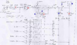
Ian, we finally have a human version of the schematic (a quasi-complete version of each channel).
(please, open it into another windows or schedule)
Some specific considerations are:
1) mic input is (normally) in opposition of phase with line input (in order to have both mic and line signals in phase after V2). In any case, when desiderable, mic input may be inverted thorugh S1.
2) R1=40 ohm, because series connected primary windings give 40 (20+20; +/- 15%) ohm DC resistence (and 600 ohm impedance).
3) On the data sheet of A262A3E it is reported that the transformer works at its best when it has 25k connected across its output when the windings are terminated in series. Consequently, for R2 has been chosen a value of 25K.
4) The components of tone control are not correct. They have to be recalculated (according to the new value of the output impedance of the previous SRPP stage (V2). To do that it is necessary know the value of output impedance (that we are not able to calculate).
5) All tubes are 6DJ8.
Some questions are:
1) Which is the output impedance of the second (V2) SRPP (with 6DJ8)?
2) Is it appropriate to insert a R-C for each Vcc (in order to decoupling individual power supply? Which values for R and C?
3) Is it opportune to parallel Vr1 and Vr5 with a little C
(...to compensate for highs loss)?
4) Can the R12 and R13 influence the tone control ? Have R12 and R13 to be eliminated ? If so, which should be value of C4 and C3 ?
5) Which value for C3 in order to obtain a 75 Hz low cut?
6) Is the value of C1, C3, C4, C10, C12, C14 ...correct?
7) Is it corrct the modified version of Aikido of V3 and V4?
An externally hosted image should be here but it was not working when we last tested it.
(please, open it into another windows or schedule)
Some specific considerations are:
1) mic input is (normally) in opposition of phase with line input (in order to have both mic and line signals in phase after V2). In any case, when desiderable, mic input may be inverted thorugh S1.
2) R1=40 ohm, because series connected primary windings give 40 (20+20; +/- 15%) ohm DC resistence (and 600 ohm impedance).
3) On the data sheet of A262A3E it is reported that the transformer works at its best when it has 25k connected across its output when the windings are terminated in series. Consequently, for R2 has been chosen a value of 25K.
4) The components of tone control are not correct. They have to be recalculated (according to the new value of the output impedance of the previous SRPP stage (V2). To do that it is necessary know the value of output impedance (that we are not able to calculate).
5) All tubes are 6DJ8.
Some questions are:
1) Which is the output impedance of the second (V2) SRPP (with 6DJ8)?
2) Is it appropriate to insert a R-C for each Vcc (in order to decoupling individual power supply? Which values for R and C?
3) Is it opportune to parallel Vr1 and Vr5 with a little C
(...to compensate for highs loss)?
4) Can the R12 and R13 influence the tone control ? Have R12 and R13 to be eliminated ? If so, which should be value of C4 and C3 ?
5) Which value for C3 in order to obtain a 75 Hz low cut?
6) Is the value of C1, C3, C4, C10, C12, C14 ...correct?
7) Is it corrct the modified version of Aikido of V3 and V4?
Attachments
Last edited:
Some specific considerations are:
1) mic input is (normally) in opposition of phase with line input (in order to have both mic and line signals in phase after V2). In any case, when desiderable, mic input may be inverted thorugh S1.
OK
2) R1=40 ohm, because series connected primary windings give 40 (20+20; +/- 15%) ohm DC resistence (and 600 ohm impedance).
3) On the data sheet of A262A3E it is reported that the transformer works at its best when it has 25k connected across its output when the windings are terminated in series. Consequently, for R2 has been chosen a value of 25K.
The 40 ohms is not necessary - it will only reduce the signal and add some noise. The A262A3 has a turns ratio of 1:6.25 and therefore transforms impedance by the square of the turns ratio i.e. 39 times. So a 600 ohm source will be reflected into the primary as 600 * 39 = 23.4K. Loading this with 25K will lose nearly half the signal. The normal rule is to load microphones with 1200 ohms of so, which reflected to the primary of this transformer is about 47K so i would recommend you change R2 to 47K.
I have never used these transformers but I see from the data sheet that the series connected primary inductance is only 0.5 Henries. With a typical 150 ohm source impedance microphone this means the -3dB point of this transformer will be about 50Hz.
4) The components of tone control are not correct. They have to be recalculated (according to the new value of the output impedance of the previous SRPP stage (V2). To do that it is necessary know the value of output impedance (that we are not able to calculate).
Provided the output impedance is low relative to the impedances of the tone control network, the exact value of the output impedance should not matter (but see below).
Some questions are:
1) Which is the output impedance of the second (V2) SRPP (with 6DJ8)?
First I have just noticed that the SRPP is being run at half the idle current of the unity gain followers (680 ohm cathode resistor vs. 300 ohms) To maintain the drive capability at the insert point I would recommend increasing the idle current in V2 by changing its cathode resistors to 300 ohms. The output impedance to a first approximation is the same as a cathode follower under the same conditions which, for a 6DJ8 running at 10mA and a 250V supply is theoretically around 100 ohms.
2) Is it appropriate to insert a R-C for each Vcc (in order to decoupling individual power supply? Which values for R and C?
Yes. Aim for a 10V dc drop in the resistor (1k for A 10mA stage) and a capacitor of 100uF should be sufficient.
3) Is it opportune to parallel Vr1 and Vr5 with a little C
(...to compensate for highs loss)?
This should not be necessary.
4) Can the R12 and R13 influence the tone control ? Have R12 and R13 to be eliminated ? If so, which should be value of C4 and C3 ?
They will not influence the tone control.
5) Which value for C3 in order to obtain a 75 Hz low cut?
This is not a good place to put a low cut filter because its operation depends on the load impedance and this is not fixed. A better place to put it would be in series with input to VR1 (50K). For -3dB at 75Hz the capacitor value would be 42.44uF. Note that the potentiometer probably has a 10% tolerance.
6) Is the value of C1, C3, C4, C10, C12, C14 ...correct?
Yes, they all look OK to me but see above about C3 (low cut)
7) Is it correct the modified version of Aikido of V3 and V4?
Yes, the changes look OK to me.
Cheers
Ian
Ian,
thank you again for your support. You are teaching a lot of things. We have also noted that you have a very clinical eye. What do you do in real life?
As to the specific points...
1)
In any case, we have not understood the solution for the 20dB PAD.
2)
3)") ). We tested the tone control section with 100 ohm output impedance ...and it has the same behaviour.
). We tested the tone control section with 100 ohm output impedance ...and it has the same behaviour.
4) . What about a second capacitor (e.i., 2.2nF) ... at the end of the circuit (after V4), in alternative (by a shitch) to C14 (1uF)? ... or in alternative to C12 (1uF), after the 50K fader?
5) Where do you suggest to put Vr3? ... on the panel (and so accessible) or into the cabinet (on the preamplifier board ... and so not accessible). In the first case... which name we should utilize to indicate its function?
6) As to all the other points ... Ok.
Ciao
Antonio and Francesco
thank you again for your support. You are teaching a lot of things. We have also noted that you have a very clinical eye. What do you do in real life?
As to the specific points...
1)
We are worried now about that transformer. We chose the A262A3 because of its low price (17 Euros) and relatively good performance on the data sheet (30Hz-25KHz). Do you have a possible solution for it? ... some suggestions or alternatives ...?I have never used these transformers but I see from the data sheet that the series connected primary inductance is only 0.5 Henries. With a typical 150 ohm source impedance microphone this means the -3dB point of this transformer will be about 50Hz.
In any case, we have not understood the solution for the 20dB PAD.
2)
Can we put the 1KR and 100uF capacitors on the power supply board ? ... or have we to put them on the preamplifier board, near the tubes?Aim for a 10V dc drop in the resistor (1k for A 10mA stage) and a capacitor of 100uF should be sufficient.
3)
You are right (always ...Provided the output impedance is low relative to the impedances of the tone control network, the exact value of the output impedance should not matter (but see below).
). We tested the tone control section with 100 ohm output impedance ...and it has the same behaviour.4)
42.44uF in series to VR1...? ...too big (as dimensions)...and too invasive (on the signal)This is not a good place to put a low cut filter because its operation depends on the load impedance and this is not fixed. A better place to put it would be in series with input to VR1 (50K). For -3dB at 75Hz the capacitor value would be 42.44uF. Note that the potentiometer probably has a 10% tolerance.
. What about a second capacitor (e.i., 2.2nF) ... at the end of the circuit (after V4), in alternative (by a shitch) to C14 (1uF)? ... or in alternative to C12 (1uF), after the 50K fader?5) Where do you suggest to put Vr3? ... on the panel (and so accessible) or into the cabinet (on the preamplifier board ... and so not accessible). In the first case... which name we should utilize to indicate its function?
6) As to all the other points ... Ok.
Ciao
Antonio and Francesco
Last edited:
I am an electronic engineer by training but I was lucky enough to retire 10 years ago at the age of 50. I have always been interested in music and recording and made my first professional recording at the age of 14, I also designed custom mixers at Neve in the mid 70s. Since retiring I have spent a lot of time recording my friend and neighbour Bob and we have released 6 albums www.thesongfactory.co.ukIan,
thank you again for your support. You are teaching a lot of things. We have also noted that you have a very clinical eye. What do you do in real life?
About three years ago I started researching tube mic preamps and now have started designing custom tube consoles Custom Tube Consoles
As to the specific points...
1) We are worried now about that transformer. We chose that because of its low price (17 Euros) and relatively good performance on the data sheet (30Hz-25KHz). Do you have a possible solution for it? ... some suggestions or alternatives ...?
In Europe the two most popular manufacturers of high quality audio transformer are Sowter and Lundahl
Both make a range of high quality microphone transformers for tube circuits but they are in the 50 to 100 Euro price range.
In any case, we have not understood which solution utilize to add a 20 dB PAD.
This is basically an attenuator that can be switched in. I will draw a sketch and post it later.
2) Can we put the 1KR and 100uF capacitors on the power supply board ? ... or have we to put them near the tubes?
They should be close to the tubes.
Whoops! That was a typing error. It should of course be 42.44nF (nanoFarads). The nearest standard values are 39nF or 47nF.4) 42.44uF in series to VR1...? ...too big (as dimensions)...and too invasive (on the signal). What about a second capacitor (e.i., 2.2nF) ... at the end of the circuit (after V4), in alternative (by a shitch) to C14 (1uF)?
Cheers
Ian
Oh, such a long time since I built valve mixers. (and most of those were round EF86s, on gromits, not pc boards; they were microphonic enough to get PA feedback without plugging in the mic.) Or heard anyone revive the Grateful Dead concept of discrete amplification.
Ignoring the question of quality required for foldback mixes (I'm frequently running monitors, and don't think the need for clarity there is any less than in the FOH rig) have you considered going whole hog with the concept and eliminating mix busses (except for monitors) and having each vocalist with his own cross over, power amps and speaker? Power is cheap enough nowadays, even if we couldn't have done it like that in the sixties (although, come to think of it, we often did. If the band had only one vocalist, no-one would dream of miking up the stacks or drums, except maybe for outdoor festivals, so every sound source was independent). With all the gain controls physically grouped, and decent balanced lines back to stage, your peak levels might be a trifle lower than you'd get out of the massed system, but the lack of intermodulation between the sources would mean you cold run into higher levels of distortion before they became audible. I don't suppose you could get hold of any tapped inductors for a switched frequency mid range control? (don't even consider trying to wind them yourself; I've done it, and it's to be avoided.
If your input transformer is a bit iffy in the low frequency coupling region make sure your input pad shows it the lowest impedance that the mics will tolerate. A mediocre quality input transformer can lose an octave of low end driven from a high source impedance (something a designer for Neve might well not know, as he never used such.)
As to sound quality you are right, but I see two limitations in your proposal: 1) the cost (each channel needs of a proper speaker too, and the speakers are not cheap enough, nowday); 2) the complexity of operation for the audio technician (it is difficult to operate with many parameters in live concert).have you considered going whole hog with the concept and eliminating mix busses (except for monitors) and having each vocalist with his own cross over, power amps and speaker? Power is cheap enough nowadays,
How?I don't suppose you could get hold of any tapped inductors for a switched frequency mid range control? (don't even consider trying to wind them yourself; I've done it, and it's to be avoided.
I know that the input transformer we chose (but not bought!) represent a problem. On the other hand, as Ian mentioned in the previous post, good transformers (Lundahal and Sowther) have relevant cost. A possible alternative could be to find a small manufacturer that realize the input transformers at low cost (but at the moment I do not know one).If your input transformer is a bit iffy in the low frequency coupling region make sure your input pad shows it the lowest impedance that the mics will tolerate.
Which source do you refer?...can lose an octave of low end driven from a high source impedance
What do you mean?(something a designer for Neve might well not know, as he never used such.)
Last edited:
I visited the website... it is very intresting and nice too.Since retiring I have spent a lot of time recording my friend and neighbour Bob and we have released 6 albums Home
1)
What about its collocation after the fader (as a switchable alterantive to the actual 1uF)? In this way we can avoid a further capacitor on the signal path (beacuse a capacitor, that of 1 uF, already exists).Whoops! That was a typing error. It should of course be 42.44nF (nanoFarads). The nearest standard values are 39nF or 47nF.
2) You forgot to reply to our point 5.
5) Where do you suggest to put Vr3? ... on the panel (and so accessible) or into the cabinet (on the preamplifier board ... and so not accessible). In the first case... which name we should utilize to indicate its function?
3) As to the vumeter (one for channel), we chose one of the following circuits:
- ELEKTRO LUKIS - Indikátor vybuzení
- VU Meter 3
... because cheap, simple, and occupying a small space on the preamplifier board (... both require only few components).
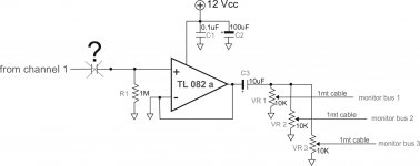
4) As to the buffer stage for monitors (where we do not think to mantein a very high audio quality) ... what do you think about the attached proposal (it seems simple, few components on the board, and a single supply (12V) ?
Is the input capacitor necessary?
5) When we'll have to bring the line-signals from the preamplifier board to the panel (e.i. potentiometers, switches, etc) which hints do you suggest to avoid signal interference ? We tought to utilize coaxial cables with the copper shield connected only on one side (to the ground star of the preamplifier board) for +ve signal line ... and (obviously) on both sides with +-ve/-ve signals.
Attachments
Last edited:
- Status
- This old topic is closed. If you want to reopen this topic, contact a moderator using the "Report Post" button.
- Home
- Live Sound
- PA Systems
- Tube mixer