lndm said:
Can you see a reason why this wouldn't work?
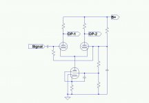
It looks like you've got some extra parts in there that you don't need. You can get rid of C3, C4, R9, and R10. Since you have a cathode current of 8.0mA, and apparantly need a bias of 1.9Vdc, then why not just use a 237R5 cathode resistor (call it 240R) and gain some extra Vpk margin? You don't really need C3 either since it's a DC application.
Then there's the main problem: can that run with a Vpk= 49.6Vdc while Vsgk= 139Vdc without poofing the screen grids? I'm not certain that you can do that.
Lastly, why would you want to? Stick a BJT cascode under there and get the better performance without any questionable, weird voltages? There was a time when you didn't have any alternatives cuz transistors hadn't been invented yet. These days, we have better alternatives, and this is a good place to consider either a BJT cascode or one of the small current IC CCS's.
Thanks, things generally improve with a second opinion.
The sim is a concept illustration and naturally will need to work with available parts. The 5879 I arbitrarily chose does not want to give up so much current with a lower Vg2. I played with a 6L6 and could manage 64V on both plate and screen with 8mA (yes, this is probably not ideal either, it's just a model I have that works)
The signal out will swing around 150Vp-p.
I am concerned that the supply rail may not be up to the task, even though it at first appears to give the goods.
No arguments, however I believe Kegger would like to follow the glass route.Miles Prower said:why would you want to? Stick a BJT cascode under there and get the better performance without any questionable, weird voltages?
Ta. Sims well.It looks like you've got some extra parts in there that you don't need.
The sim is a concept illustration and naturally will need to work with available parts. The 5879 I arbitrarily chose does not want to give up so much current with a lower Vg2. I played with a 6L6 and could manage 64V on both plate and screen with 8mA (yes, this is probably not ideal either, it's just a model I have that works)
The signal out will swing around 150Vp-p.
I am concerned that the supply rail may not be up to the task, even though it at first appears to give the goods.
Thanks for the Pic there Lndm and nudge of the glass thingy. ")
Yes I would like to do the all glass route, nothing against solid state
pieces but want to do it with tubes that's all.
And I'm not looking for perfection or the best way to do it, but just
something that will work and work better then just a grounded tail.
So I'm still experimenting with the triode version and want to see if
I can make it work better then just the grounded tail version if I can.
- Status
- This old topic is closed. If you want to reopen this topic, contact a moderator using the "Report Post" button.