They convert the current to voltage.What do the I/V resistors actually do
The larger the current the higher the voltage across the resistors.
And the other way around. Lower current...lower voltage.
Last edited:
They convert the current to voltage.
The larger the current the higher the voltage across the resistors.
And the other way around. Lower current...lower voltage.
I'll never understand electricity, probably because I'm a carpenter, well I used to be.
There is some nice tutorials/explanations on the IntarrwebsI'll never understand electricity, probably because I'm a carpenter, well I used to be.
")
Welcome to the Electronics Club
EEVblog
Adafruit Learning System
for example.
Any PCB available?
Hi Andrea,
the Tube-I-zator pcb is in Stock. If you want to order, please send me a PM with your paypal address and the quantity you need.
Best regards,
Oliver
I'm interested but wasn't sure what the latest BOM was without going through 72 pages
Good idea! I´ve added the information to post #1.
Oliver

Good idea! I´ve added the information to post #1.
Oliver
Thanks!
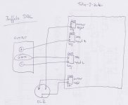
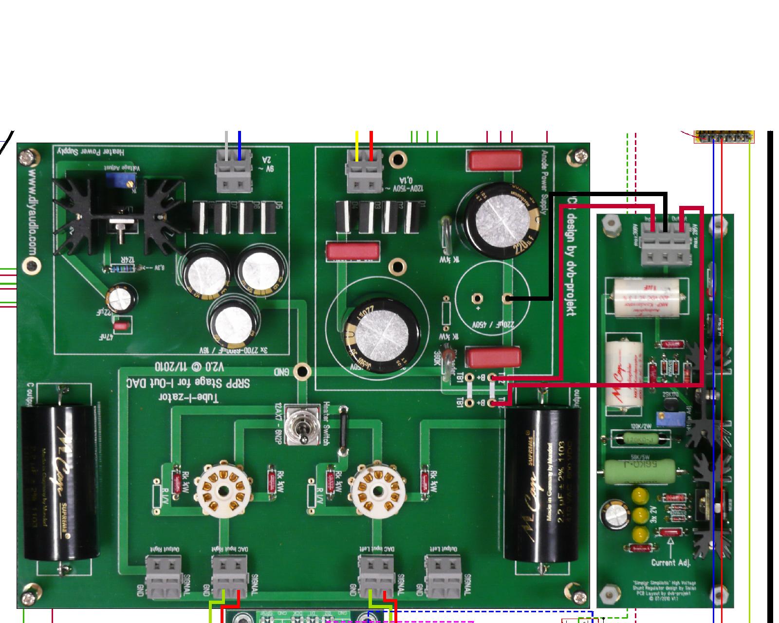
I was hoping somebody might be able to confirm I have the wiring right.
Do I need to connect the central ground point to the case or even to the AC earth point?
Do I need to connect the central ground point to the case or even to the AC earth point?
Attachments
Last edited:
I was hoping somebody might be able to confirm I have the wiring right.
Do I need to connect the central ground point to the case or even to the AC earth point?
Everything perfect! I would connect the central GND to your star GND point of the case.
Oliver
Oliver has kindly sold me a couple of the tube-i-zator boards and I've got them working individually just using a single ended output from the dac (basically, for L and R channels connecting the negative line of the balanced output to the gnd and then using negative/ground and positive to connect to the Tube-i-zator input. This sounds great!
Then I tried to connect the one dac board to the two tube-i-zator boards. My idea was that each board would do one channel. On one board, the positive part of the balanced output from the DAC would be connected to the input marked left and the negative part of the balanced circuit would be connected to the right input. The other tube-i-zator board would be used for the other channel.
I wasn't entirely blown away by the sounds quality so I thought I must have connected things up incorrectly. I saw Headrott's dual mono set up here: http://www.polkaudio.com/forums/showthread.php?119264-Fully-balanced-Buffalo-II-DAC-with-Tube-I-zator-tube-output.
It looks like he's taking the different sides of the balanced outputs from different tube-i-zator boards - in other words he's splitting the L and R +/- across the two boards. I'm sure it's not going to do any harm but I'm not sure why. Can anyone explain why? And also tell me if I'm doing it wrong ;-)
My second problem is that I'm having difficulty matching the gain across the two tube-i-zator boards - even when using a matched quad of valves. The mismatch isn't huge but noticeable. I'm wondering whether this might be why Headrott wired it up as he had.
Any help would be most appreciated. I want to stop fiddling (at least for a bit) and listen to some music ;-)))
Oliver has kindly sold me a couple of the tube-i-zator boards and I've got them working individually just using a single ended output from the dac (basically, for L and R channels connecting the negative line of the balanced output to the gnd and then using negative/ground and positive to connect to the Tube-i-zator input. This sounds great!
Then I tried to connect the one dac board to the two tube-i-zator boards. My idea was that each board would do one channel. On one board, the positive part of the balanced output from the DAC would be connected to the input marked left and the negative part of the balanced circuit would be connected to the right input. The other tube-i-zator board would be used for the other channel.
I wasn't entirely blown away by the sounds quality so I thought I must have connected things up incorrectly. I saw Headrott's dual mono set up here: http://www.polkaudio.com/forums/showthread.php?119264-Fully-balanced-Buffalo-II-DAC-with-Tube-I-zator-tube-output.
It looks like he's taking the different sides of the balanced outputs from different tube-i-zator boards - in other words he's splitting the L and R +/- across the two boards. I'm sure it's not going to do any harm but I'm not sure why. Can anyone explain why? And also tell me if I'm doing it wrong ;-)
My second problem is that I'm having difficulty matching the gain across the two tube-i-zator boards - even when using a matched quad of valves. The mismatch isn't huge but noticeable. I'm wondering whether this might be why Headrott wired it up as he had.
Any help would be most appreciated. I want to stop fiddling (at least for a bit) and listen to some music ;-)))
Hi,
you could see the balanced connection scheme attached for one channel.
If you are using a matched quad of tubes, identical B+ voltages and 1% tol. (or better) Rk and R i/v resistors, there should be no gain differences!
Attachments
I cant believe it's taken this long to get this far
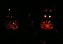
Anyway I have the tubes glowing as you will see, but I have a couple of questions.
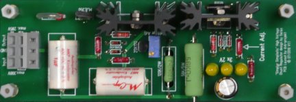
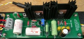
When I adjust the output voltage from the SSHV to 150V as advised the input voltage is 160V, I read somewhere that there was suppose to be a larger difference between the two. The A/C coming from the 150V secondary is actually 154V.
On the SSHV the heat sink closes to the input/output is too hot to touch where the other heat sink is just warm, is this normal?
And lastly is it normal for the heater elements to glow brightly for about a second when you first turn it on?
Anyway I have the tubes glowing as you will see, but I have a couple of questions.
When I adjust the output voltage from the SSHV to 150V as advised the input voltage is 160V, I read somewhere that there was suppose to be a larger difference between the two. The A/C coming from the 150V secondary is actually 154V.
On the SSHV the heat sink closes to the input/output is too hot to touch where the other heat sink is just warm, is this normal?
And lastly is it normal for the heater elements to glow brightly for about a second when you first turn it on?
Attachments
Last edited:
I cant believe it's taken this long to get this far
Anyway I have the tubes glowing as you will see, but I have a couple of questions.
When I adjust the output voltage from the SSHV to 150V as advised the input voltage is 160V, I read somewhere that there was suppose to be a larger difference between the two. The A/C coming from the 150V secondary is actually 154V.
On the SSHV the heat sink closes to the input/output is too hot to touch where the other heat sink is just warm, is this normal?
And lastly is it normal for the heater elements to glow brightly for about a second when you first turn it on?
What is your DC after the rectifier and without the SSHV in place?
What is your DC after the rectifier and without the SSHV in place?
That was fast, 228V
Did you have a wire (the yellow one) joining tb1 and tb2 like here?
Otherwise only one tube gets the B+!

I had miss this on your picture here...
No I seem to have forgotten the yellow wire
I will make changes tonight & report back.
any thoughts on the other questions
On the SSHV the heat sink closes to the input/output is too hot to touch where the other heat sink is just warm, is this normal?
And lastly is it normal for the heater elements to glow brightly for about a second when you first turn it on?
- Status
- This old topic is closed. If you want to reopen this topic, contact a moderator using the "Report Post" button.
- Home
- Group Buys
- Tube-I-zator Professional PCB