Re: it didn t work 
Have you made sure it's all connected properly?, try fault finding, it's a very simple circuit.
When you say it doesn't work, what doesn't work?.
Ahmad_tbp said:it didn t work ...
i changed the two input couplage caps to 47n and the output couplage cap to 1uf , and use it before pre ,
it didn t work !
any idea ???????
Have you made sure it's all connected properly?, try fault finding, it's a very simple circuit.
When you say it doesn't work, what doesn't work?.
i mean it doesn t work correctly ...
it s a very loud sawtooth or square wave around 80/100 hz ( i m not sure bout the wave and freq , i don have a scope ) comin out of it , but when i turn the 2nd pot (25k) all the way down the noise become silence suddenly , i connected my signal generator to it , very very little pulsin sound come out of it !!!
...it s a very loud sawtooth or square wave around 80/100 hz ( i m not sure bout the wave and freq , i don have a scope ) comin out of it , but when i turn the 2nd pot (25k) all the way down the noise become silence suddenly , i connected my signal generator to it , very very little pulsin sound come out of it !!!
Ummm, what else can cause this... transistor in backwards or one that's leaky, R/C time constant too short (getting FB through the LED/LDR), which can also happen with correct R/C if the LDR is in the wrong spot in the circuit and finally, the 3900 is a hi-Z device - incorrect wire dressing wreaking havoc.
no man ! i m talkin bout the valve comp/limiter schematic i sent , i built it , ...transistor in backwards or one that's leaky, R/C time constant too short (getting FB through the LED/LDR),
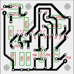
here s the pcb , maybe i make a mistake and didn t seen it
Attachments
Ahmad_tbp said:
no man ! i m talkin bout the valve comp/limiter schematic i sent...
Ah, OK!
Then what you're describing is powersupply ripple. It needs a superclean supply and good decoupling.
Ahmad_tbp said:
here s the pcb , maybe i make a mistake and didn t seen it
Just wondering?, why make a PCB and then not mount the valve holders on it? - it seems rather a waste of time?. If you're mounting the valve holders on a chassis, why not hand wire them? - in classical valve fashion (particularly for something as simple as this).
The old TV manufacturer KB actually manufactured valve colour TV sets all hand wired without PCB's! - incredible what you can do!.
wat if i use this power supply ?
http://www.diyaudio.com/forums/attachment.php?s=&postid=890290&stamp=1144698398
http://www.diyaudio.com/forums/attachment.php?s=&postid=890290&stamp=1144698398
Re: the problem is transformer
You would need about 0.6A if you ran the heaters on 6.3v(one heater supply lead to pins 4 and 5 and the other lead to pin 9) or 0.3A if you run the heaters on 12.6v(one heater lead to pin 4 and the other lead to pin 5, pin 9 not connected).
In my experience I like to use AC for the heaters with the heater winding raised ~40v DC above ground. The easiest way to do this is to use a center tapped heater winding. Rather than connecting the center tap to ground, connect it to 30-60v DC from your B+ supply(hint: use a voltage divider off of one of your B+ taps).
If you don't have a tranny with a center tapped heater winding, you can still raise the DC component of the heater supply with respect to ground. To do this you need to create a virtual center tap by wiring 2 100-150ohm resistors in series between the heater leads, then you can connect the 30-60v DC supply to the virtual center tap created by the resistors(in between the two resistors).
Doing this should help decrease the hum introduced by the AC heaters. If raising the heater supply to 30-60V DC with respect to ground doesn't help or creates more hum, you could try applying a negative voltage with respect to ground to the heater supply center tap or virtual center tap.
If you decide to try this and you have never attempted this before, I would recommend that you use cheap tubes incase you accidently fry the heaters. Also you need to look up the data sheet for each tube type that is connected to that heater supply and make sure that they can handle the voltage you are applying to the heater supply. You can look up the data sheets on www.nj7p.org/Tube.php and look for "Maximum Heater-Cathode Voltage: Heater Positive with Respect to Cathode". That is the maximum voltage you can apply to your heater winding before the heater will arc to other internal components in the tube.
In my experience, the method above is alot easier than DC because with DC heaters you will need a beefy rectifier bridge with a large heat sink, and you will need lots of filtering, I tend to use about 10,000uF for every amp of current the heaters require.
-RancidAltoid
Ahmad_tbp said:hi .. i think my problem is my transformer ...
lemme see if i can find a transformer and change it to c wat will happen
how much Amper do i need for flaments ? and wat s better if i use dc or ac ???
You would need about 0.6A if you ran the heaters on 6.3v(one heater supply lead to pins 4 and 5 and the other lead to pin 9) or 0.3A if you run the heaters on 12.6v(one heater lead to pin 4 and the other lead to pin 5, pin 9 not connected).
In my experience I like to use AC for the heaters with the heater winding raised ~40v DC above ground. The easiest way to do this is to use a center tapped heater winding. Rather than connecting the center tap to ground, connect it to 30-60v DC from your B+ supply(hint: use a voltage divider off of one of your B+ taps).
If you don't have a tranny with a center tapped heater winding, you can still raise the DC component of the heater supply with respect to ground. To do this you need to create a virtual center tap by wiring 2 100-150ohm resistors in series between the heater leads, then you can connect the 30-60v DC supply to the virtual center tap created by the resistors(in between the two resistors).
Doing this should help decrease the hum introduced by the AC heaters. If raising the heater supply to 30-60V DC with respect to ground doesn't help or creates more hum, you could try applying a negative voltage with respect to ground to the heater supply center tap or virtual center tap.
If you decide to try this and you have never attempted this before, I would recommend that you use cheap tubes incase you accidently fry the heaters. Also you need to look up the data sheet for each tube type that is connected to that heater supply and make sure that they can handle the voltage you are applying to the heater supply. You can look up the data sheets on www.nj7p.org/Tube.php and look for "Maximum Heater-Cathode Voltage: Heater Positive with Respect to Cathode". That is the maximum voltage you can apply to your heater winding before the heater will arc to other internal components in the tube.
In my experience, the method above is alot easier than DC because with DC heaters you will need a beefy rectifier bridge with a large heat sink, and you will need lots of filtering, I tend to use about 10,000uF for every amp of current the heaters require.
-RancidAltoid
hi Rancid Altoid , thnx ..
sorry i m so new in tubes , but i think u r talking bout hum balance ,?
if i m not wrong hum balance is for transformer without a center tap fo 6.3 v , but i ordered 2 transformer with 250-0-250 , 250ma for pre and comp B+ , and 8-0-8 ,2A for heaters , i m going to use regulator to feed heatres with 6.3v DC voltage - i know it will become more expensive , but i never had experience with tubes before so it will be easier for me to use DC and get rid of hum , and i have more experience with dc voltage and how to regulator and filter it .
just one thing else . u siad if i m goin to use 12.6v dc i have to connect it to pin 4,5 and leave pin 9 unconnected to anything ???
wow i connected pin4,5 together and lead it to one heater and lead other to pin9 in my preamp , wow thanks god i didn t blow up the tube !
sorry i m so new in tubes , but i think u r talking bout hum balance ,?
if i m not wrong hum balance is for transformer without a center tap fo 6.3 v , but i ordered 2 transformer with 250-0-250 , 250ma for pre and comp B+ , and 8-0-8 ,2A for heaters , i m going to use regulator to feed heatres with 6.3v DC voltage - i know it will become more expensive , but i never had experience with tubes before so it will be easier for me to use DC and get rid of hum , and i have more experience with dc voltage and how to regulator and filter it
.just one thing else . u siad if i m goin to use 12.6v dc i have to connect it to pin 4,5 and leave pin 9 unconnected to anything ???
wow i connected pin4,5 together and lead it to one heater and lead other to pin9 in my preamp , wow thanks god i didn t blow up the tube !
If you look at the pin out, pins 4 and 5 of the 12ax7 are the ends of the heater with pin 9 being the center tap. Since it is a 12.6 volt tube, you can either supply 12.6 volts across pins 4 and 5 with pin 9 disconnected or you can supply 6.3 volts across pins 4 and 9, and pins 5 and 9. Does that make sense to you?
-RancidAltoid
-RancidAltoid
Hello.
I am also a novice in building with tubes.
I am trying to build the compressor based on the schematics mr Ahmad supplied us with here in this thread.
I have a couple of questions.
1. On the original schematics ground is marked and this is the negative point I guess.
Another point marked "HT" is at the top right.
I guess
this is where the positive feed to the circuit is to be placed. How much in voltage/ampere is the circuit operating on. Is it 220V=, 220V~ or just the heater current 6.3 V~?
2. Can I use just one transformer 6.3 V~ on pin 4+5 and 9 on both tubes?
3. What kind of resistors is to be used? Metallfilm for low noise or common carbon types. Or is the effect so big that I have to use effect resistors?
Anyone who knows about this please reply and you will help me out alot.
Thank you, All the best/Fredrik E.
P.s. I attached the schematics here again. Thanks.
Attachments
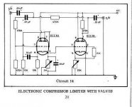
Tube Compressor **CIRCUIT 14 DIAGRAM**
Hello,
I am a novice in building tube compressors, or anything derived from schematic diagrams for that matter. I searched on the internet for shematics and I came accorss the same diagram as those you have been building.
I was wondering:
1) what voltage do the capacitors need to be?
2) How strong the voltage of the transformer should be?
Also I have never built anything electronic from scratch, so I have no knowledge of AC or DC, regarding how they operate, so I was wondering what would be easier and produce the best sound? the least amount of hum. Any information would be of great help. Thanks.
Ahmad_tbp said:hi
i m wanted to start building a tube compressor for my bass guitar , i found a compressor schematic with two ecc83 , but it seems it s too old ,and i confused bout the pin connection in first tube , it seems somebody draw it after the original schematic , can anybody tell me , are pin2 and pin1 directly connected to together on first tube ? ( i shown it with a red line around it )
sorry i didn t remember the original link of schematic and the image has no info or copyright on it so i attached the photo ,...
--any idea for another compressor ? any mods ?
Another option is to add an opto pair to your existing amp; a LED and a photo resistor.
- Status
- This old topic is closed. If you want to reopen this topic, contact a moderator using the "Report Post" button.
- Home
- Live Sound
- Instruments and Amps
- Tube Compressor