It's output resistance is high. And what for is the potentiometer at output? It makes things worse.
Why are you going to use buffer for CD player? What problem with CD player do you have?
What DAC chip do you have in this CD player? Maybe modification of analogue stage of your CD makes sense?
Why are you going to use buffer for CD player? What problem with CD player do you have?
What DAC chip do you have in this CD player? Maybe modification of analogue stage of your CD makes sense?
Hi McGyver!It's output resistance is high. And what for is the potentiometer at output? It makes things worse.
Why are you going to use buffer for CD player? What problem with CD player do you have?
What DAC chip do you have in this CD player? Maybe modification of analogue stage of your CD makes sense?
I have a CD-player Technics want between the amplifier LM3886 to set the tube buffer for to get the tube sound!
")
If you have some good schematics or project with buffers (or catode follower) with tube 6n8s (6n7) or 6n3 only please!
Thank you for your cooperation!
P.S.
This is the original schematics: (view photos)
Attachments
Last edited:
The original circuit is poor; the OP's mod is worse. Far too much gain, and a bass boost! This is not a 'tube buffer'.
Find a circuit which works, and build it unmodified. That is my advice. Alternatively, learn how to design/modify circuits yourself. Don't keep putting up copyright infringements and demanding that we improve them for you.
Find a circuit which works, and build it unmodified. That is my advice. Alternatively, learn how to design/modify circuits yourself. Don't keep putting up copyright infringements and demanding that we improve them for you.
The tube buffer between a source and amp can only spoil the signal quality and never improve. If you are unhappy with sound quality from your Technics CD player, then sell it on ebay, buy cheap Denon based on PCM56 or PCM61 and replace it's analogue stage with passive conversion followed by tube gainstage. The working example you can find on my site: Odtwarzacze CD (must do some scroll down).
Hi ,The tube buffer between a source and amp can only spoil the signal quality and never improve. If you are unhappy with sound quality from your Technics CD player, then sell it on ebay, buy cheap Denon based on PCM56 or PCM61 and replace it's analogue stage with passive conversion followed by tube gainstage. The working example you can find on my site: Odtwarzacze CD (must do some scroll down).
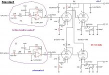
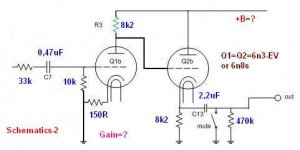
I want the output of a CD-player to connect tube buffer (Schematics-1 or schematics-2)?
Which of these schematics is preferred.
In the first schematics of what needs to be changed if you replace the 6n3 with 6n8s?
What anode voltage + B =? should be
In the schematics if it is placed 6n8s which values should be on the schematics?
What anode voltage + B =?
P.S.
With this tube buffer (circuit) I want to get a nice tube/valve sound !!
Thank you for your cooperation.
Cheers!
Attachments
Last edited:
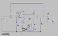
This is what I would do.
This of course has quite a lot of gain, so this could (should) be driven straight from the DAC output. Output can drive pretty much anything no problem.
MOSFETs can be for example IRF820 or IRF840, or some other high voltage MOSFET.
This could be just barely ok with B+ of 200 volts, but 250 is preferable. Plate voltage of around 140 volts gives a steady 12mA thru the tube, so the cathode bias diodes are happy with no extra current supplies.
This would give a really good sound, but don't know about the tube sound though. I'd venture to say much better than the op amp output in DACs.
Attachments
How much gain is "a lot of"?This is what I would do.
This of course has quite a lot of gain (...)
Looking at the datasheet the 6N3P has a mu of about 35.
With the plate load in my schematic, the gain of the circuit (the MOSFET follower has no gain) is equal to the mu.
My DAC chip puts out (max) 127mV, so if I had this circuit as the output, it would put out over 4 volts peak.
With the plate load in my schematic, the gain of the circuit (the MOSFET follower has no gain) is equal to the mu.
My DAC chip puts out (max) 127mV, so if I had this circuit as the output, it would put out over 4 volts peak.
Like I said; quite a lot of gain.
35 volts is a solid, good level for most triode output tubes; not excessive by any stretch. If your chip has that high output, then you've got a good whole system then. Chip to preamp to output stage. The MOSFET source follower in my schematic is a very good way to drive an output triode grid.
With lower output chips one still needs a gain stage before the output stage.
I'm not entirely sure what a 'buffer' is meant to be according to the OP. In my own opinion a buffer would be just the MOSFET source follower section of my schematic. Triodes have gain, so when you want to use them, you'll have gain. The OP said he wanted to use 6N3P, and I showed what I'd do with that tube.
Perhaps a triode like 6C19 with a mu of 2 would be a good buffer.
It all depends on how you plan your gain structure for the whole system.
yes indeed, but only in case if whole of your system will be DIY. And this scenario is rather not for newbies.
But your circuit may be improper when one going to use a commercial solid state amplifier.
BTW, I like your circuit and I consider to give it a try with my AD1865 DAC with passive I/V (in this case C2 should be omitted). There will be about 2V of output signal level with 100 ohm or so conversion resistor.
Thanks! I have a AD1865 DAC, with a different tube in the output (directly heated 2J27 triode strapped). C2 is redundant in many situations; I usually have fixed grid bias when single ended so I just have it in the scheme.
The OP's situation is - though common - a bit difficult. He probably has a CD player with a line level opamp output, and a transistor amp that can go full power on a line level signal. So he basically doesn't need any gain at all.
However, the "line buffer" or preamp or whatever, is usually the first thing to DIY, to get a taste. It'll be completely redundant, but exciting to make, and learn.
Best case, the new DIYer will realise that tubes are not for 'sound' but for fidelity. This of course presupposes a lot of learning while making.
Hi guys!
There is no confusion here's what I need (see schematics-1F).
Thank's!
Attachments
Last edited:
Yes, yes, for I get it a good tube sound!!As I stated before, insertin a buffer between source and amp can only affect the sound, and not to improve. Are you sure you want affect sound quality in your system?
Much like even harmonics (2-second, 4-fourth,... etc.) to <-60dB!
Cheers!
Last edited:
- Home
- Amplifiers
- Tubes / Valves
- Tube buffer with 6n3-EV