revintage said:Does anyone have an electrical model of a typical ESL-panel? This would make it easier to do a lot of the prototyping in Pspice. Do not think the model is as easy as just a capacitor.
Your hunch that an electrostatic speaker's input impedance is not as simple as just a capacitance is right on. The input impedance of an electrostatic speaker is as complicated as that of a cone speaker, depending upon many factors, not the least of which is the radiation impedance seen by the speaker (a nearby wall or object affects this). F.V. Hunt published an analysis on this topic years ago, and I've posted a composite of his equivalent circuit and impedance plots in polar coordinate form. Your next question might be "what are the typical values for each component". My answer is that there really are no typical values. Sorry, this won't be easy to plug into PSpice; there are just too many variables.
Attachments
revintage said:The step-up transformers is around 1:50 I guess (4:10000 ohms). And for some reason they do not use the center-tap for the EHT, it is connected to one of the secondaries. Can supply you with a schematic of filter and transformer later today.
Brgds
Lars [/B]
Have now measured the tranny with 1kHz and it is 1:70.
Brian Beck said:
F.V. Hunt published an analysis on this topic years ago, and I've posted a composite of his equivalent circuit and impedance plots in polar coordinate form.
Great Brian! Can I humbly ask for the sides before and after from this analysis?
I have made a schematic of one half of the bridged amp:
www.revintage.se/ESLDD3.pdf
A cascode Mu-stage driving a SRPP with triode in the upper half and pentode in the lower.
Have also attached a schematic of what is hiding inside the ML Script
Attachments
Modulation transformer from AM broadcast transmitter with ES speaker?
I haven`t read this entire thread but a search did not yield an answer.
I would like to know if anyone has any experience trying to use a plate modulation transformer to directly drive electrostatic loudspeaker panels, with the usual HV DC bias supply for the panel of course.
A plate modulation xfmer is just like a normal P-P output xfmer except instead of a low Z speaker winding for the output secondary it has a high-Z winding (often several thousand ohms), insulated for high voltage which impresses the audio modulation of the modulator to the B+ which goes to supply the transmitter`s output RF power amp tube(s).
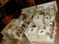
I have a pair of really nice 1950 audio modulators from two identical vintage RCA, AM broadcast transmitters which use a pair of 809 triodes in p- p to make about 50 Watts RMS audio output power. If I replace the output transformer, a Hi-Z modulation xfmer with a normal P-P iron I could have a conventional amplifier.
I would like to know if I can use the existing modulation xfmers in a specialized application, like driving ES loudspeakers.
I do know that my modulators would be ideal to plate modulate a RF power triode used as power oscillator to power a plasma speaker. Plate modulation is more expensive and complicated but produces the lowest distortion compared to other modulation methods, like screen modulation as an example.
Pic of my two power supplies and two modulator amplifiers shown. There is more high quality oil filled iron here than in the Exxon Valdez.
I haven`t read this entire thread but a search did not yield an answer.
I would like to know if anyone has any experience trying to use a plate modulation transformer to directly drive electrostatic loudspeaker panels, with the usual HV DC bias supply for the panel of course.
A plate modulation xfmer is just like a normal P-P output xfmer except instead of a low Z speaker winding for the output secondary it has a high-Z winding (often several thousand ohms), insulated for high voltage which impresses the audio modulation of the modulator to the B+ which goes to supply the transmitter`s output RF power amp tube(s).
I have a pair of really nice 1950 audio modulators from two identical vintage RCA, AM broadcast transmitters which use a pair of 809 triodes in p- p to make about 50 Watts RMS audio output power. If I replace the output transformer, a Hi-Z modulation xfmer with a normal P-P iron I could have a conventional amplifier.
I would like to know if I can use the existing modulation xfmers in a specialized application, like driving ES loudspeakers.
I do know that my modulators would be ideal to plate modulate a RF power triode used as power oscillator to power a plasma speaker. Plate modulation is more expensive and complicated but produces the lowest distortion compared to other modulation methods, like screen modulation as an example.
Pic of my two power supplies and two modulator amplifiers shown. There is more high quality oil filled iron here than in the Exxon Valdez.
Attachments
revintage said:Great Brian! Can I humbly ask for the sides before and after from this analysis?
I'd like to help, but F.V. Hunt's analysis is a long and rigorous march of 44 pages on electrostatic transducers, that builds on previous chapters needed for full comprehension. Posting one or two more pages won't help, and I don't want to get into copyright infringement beyond "fair use". The book is currently published (reprinted) by the American Institute of Physics for the Acoustical Society of America (or it was when I bought it several years ago).
Anyone with reasonable technical and mathematical skills who is serious about understanding electrostatic transducer theory should consider buying the book. It's not an easy ride, but Hunt published the most rigorous analyzes available on the subject, at least to my knowledge:
Electroacoustics by F.V. Hunt
Re: Modulation transformer from AM broadcast transmitter with ES speaker?
RCAvictim,
That's a very interesting idea! In an earlier thread we had discussed a similar notion:
http://www.diyaudio.com/forums/showthread.php?postid=931639#post931639
When we use a tube amp to drive an ESL, we usually have a regular OPT to step down to 8 ohms, followed by a step-up transformer to maybe tens or hundreds of kilo-ohms equivalent. Wouldn't it make more sense to use a single step-up transformer of maybe 1:3 or 1:5 to interface tube plates to stators more directly?
I hadn't thought of using an AM plate modulation transformer, but that may work well. What is the turns ratio of your transformers? Usually the secondary would have had to pass DC plate current for the RF final stage, so the core must be seriously gapped. I don't know how much that reduced primary inductance and restricted bass, but if you're not driving full-range ESLs, the gapping may be OK. Also, there's no telling what the high-frequency characteristics are like. The designers may not have cared about modulation signals above 6 or 10KHz.
But, hey, it's worth a try!
EDIT: PS:
Yes, and it's probably PCB oil! Watch out for leaks!
rcavictim said:I would like to know if anyone has any experience trying to use a plate modulation transformer to directly drive electrostatic loudspeaker panels, with the usual HV DC bias supply for the panel of course.
RCAvictim,
That's a very interesting idea! In an earlier thread we had discussed a similar notion:
http://www.diyaudio.com/forums/showthread.php?postid=931639#post931639
When we use a tube amp to drive an ESL, we usually have a regular OPT to step down to 8 ohms, followed by a step-up transformer to maybe tens or hundreds of kilo-ohms equivalent. Wouldn't it make more sense to use a single step-up transformer of maybe 1:3 or 1:5 to interface tube plates to stators more directly?
I hadn't thought of using an AM plate modulation transformer, but that may work well. What is the turns ratio of your transformers? Usually the secondary would have had to pass DC plate current for the RF final stage, so the core must be seriously gapped. I don't know how much that reduced primary inductance and restricted bass, but if you're not driving full-range ESLs, the gapping may be OK. Also, there's no telling what the high-frequency characteristics are like. The designers may not have cared about modulation signals above 6 or 10KHz.
But, hey, it's worth a try!
EDIT: PS:
There is more high quality oil filled iron here than in the Exxon Valdez
Yes, and it's probably PCB oil! Watch out for leaks!
Brian Beck said:
The book is currently published (reprinted) by the American Institute of Physics for the Acoustical Society of America (or it was when I bought it several years ago).
Will order at once! Seems to be the loudspeaker bible.
Thanks
Lars
revintage said:Will order at once! Seems to be the loudspeaker bible.
Good. I don't know if I'd call the rest of the book "the loudspeaker bible", though. It's a rather idiosyncratic book, picking and choosing its topics in a less-than comprehensive way. But, again, for ESL understanding, it's required reading for math-oriented types.
Re: Re: Modulation transformer from AM broadcast transmitter with ES speaker?
Brian,
Thanx for the reply. I hadn`t considered that these mod xfmers would use gapped cores but you are absolutely right. Interesting. I wonder what else one could do with them as a result. One idea is a SE to P-P (or SE) grid driver xfmer for a large class A2 output stage. Operating at reduced current would improve the bass extension!
I need to slide these amps out from under the bench and measure the transformers as you suggest.
Fortunately none of the xfmers has any seepage or leaks. It is my opinion that the only hazard from PCB oil is not from contact with the oil, but from contact with the EPA when they discover you are in possession of it.
Brian Beck said:
RCAvictim,
That's a very interesting idea! In an earlier thread we had discussed a similar notion:
http://www.diyaudio.com/forums/showthread.php?postid=931639#post931639
When we use a tube amp to drive an ESL, we usually have a regular OPT to step down to 8 ohms, followed by a step-up transformer to maybe tens or hundreds of kilo-ohms equivalent. Wouldn't it make more sense to use a single step-up transformer of maybe 1:3 or 1:5 to interface tube plates to stators more directly?
I hadn't thought of using an AM plate modulation transformer, but that may work well. What is the turns ratio of your transformers? Usually the secondary would have had to pass DC plate current for the RF final stage, so the core must be seriously gapped. I don't know how much that reduced primary inductance and restricted bass, but if you're not driving full-range ESLs, the gapping may be OK. Also, there's no telling what the high-frequency characteristics are like. The designers may not have cared about modulation signals above 6 or 10KHz.
But, hey, it's worth a try!
EDIT: PS:
Yes, and it's probably PCB oil! Watch out for leaks!
Brian,
Thanx for the reply. I hadn`t considered that these mod xfmers would use gapped cores but you are absolutely right. Interesting. I wonder what else one could do with them as a result. One idea is a SE to P-P (or SE) grid driver xfmer for a large class A2 output stage. Operating at reduced current would improve the bass extension!
I need to slide these amps out from under the bench and measure the transformers as you suggest.
Fortunately none of the xfmers has any seepage or leaks. It is my opinion that the only hazard from PCB oil is not from contact with the oil, but from contact with the EPA when they discover you are in possession of it.
...but from contact with the EPA when they discover you are in possession of it.
I won't tell them, promise. I have several chucks of iron that have PCBs within them, and I keep a wary eye on them.
I wouldn't let the gapping turn you off. Let's see what you measure. I think the idea has real merit. The turns-ratio will be of primary (pun) importance of course. The secondary is probably not center-tapped, so to bias the ESL diaphragm, you'll need to create a pseudo-CT with a pair of high-value resistors. No big deal.
In fact, there may a number of complete old plate-modulation tube amps that are ready for direct ESL use as-is (or almost as-is). What a thought! Now we may have created a run on modulation amps. I've got some old mod amps myself in my musty pile of boatanchor carcasses, and probably some modulation transformers too. If I had any free time, I'd look them over. Please report what you measure in your own amps.
Brian Beck said:
The secondary is probably not center-tapped, so to bias the ESL diaphragm, you'll need to create a pseudo-CT with a pair of high-value resistors.
Don´t know if you checked the Script schematic where they have connected the bias to one end of secondaries and left the CT unused! It works anyway, maybe the small potential difference between the taps is neglible.
Is there anyone who have checked how high the signal levels in music is over 500Hz in comparision to fullrange?
revintage said:
Don´t know if you checked the Script schematic where they have connected the bias to one end of secondaries and left the CT unused! It works anyway, maybe the small potential difference between the taps is neglible.
Is there anyone who have checked how high the signal levels in music is over 500Hz in comparison to fullrange?
No, I haven't seen the Script schematic. Can you post it?
The more I think on it, the more I think that biasing the diaphragm will not be the issue with a no-CT modulation transformer; instead it will be anchoring the center point for driving the ESL stators. I think you'd need lower value resistors to create a virtual center tap to force the push-pull drive behavior. I think these resistors would have to be lower than the impedance of the ESL at all working frequencies. That's then the Achilles heel of a modulation transformer without a secondary CT, I believe. But still, it may be worthwhile.
Regarding your question about spectral distribution, for orchestral music I seem to recall that 500 Hz was about the energy centroid; that is to say that there is equal average energy below 500Hz as above it. For rock and other kinds of music, the centroid may be a bit higher.
Brian Beck said:
No, I haven't seen the Script schematic. Can you post it?
The more I think on it, the more I think that biasing the diaphragm will not be the issue with a no-CT modulation transformer; instead it will be anchoring the center point for driving the ESL stators.
Thank you for all useful information.
Here is the scematic again
") (attached it in one of my posts yesterday). Just got a schematic from ML so I have double-checked. The funny thing is that the transformer is CT with the tap isolated and unused.
(attached it in one of my posts yesterday). Just got a schematic from ML so I have double-checked. The funny thing is that the transformer is CT with the tap isolated and unused. On the HV card there is 60Mohm in series with the HV. Checked with ML and they told med that the voltage is 2.4kV. Will measure with a probe to verify. Rather high for a mid/treble panel, isn´t it?
The speaker plays loud enough for me with a 30W/6ohm amplifier. Lets assume that the impedance is 4 ohm on the primary taps(nominal impedance 6 ohm-2 ohm series) at midfrequencies and half of the power into the Script is over 500Hz. We will then have a signal-voltage of 9.5V(10W 4ohms) on the primary taps and 700V on the panel.
My suggested amp theoretically swings 600Vrms at clipping with 1000V B+ so it will need to work at 1200V to handle the peaks. This would also mean that ca 15mA of current is needed into the load, if it was purely resistive. But how much will be needed into this complex load?
As the amplifier is bridged, each half of it must deliver this current. With an efficiency of 25% this means the power supply will have to deliver around 40mA.
Have done a lot of guess-work here, but I hope that at least some of it is correct.
Attachments
Error in last post
Made an error in last post about signal. Hope this is right:
With 30W into 6ohms, where we assume that half power is above 500Hz and half below, we get a signal of 9.5V into 6 ohms.
One third of the signal is burned in the 2ohm series-resistor leaving us with 6,3V=10W into 4ohm (if this is the primary-impedance of the transformer).
With the 1:70 transformer this means 450V rms on the panel. So we can now go down to 750V B+ and need around 25mA/side in the bridged amp.
With a 50W total into 6ohms there is ruffly 18W on the panel and we need 1000V B+ and 35mA/side for the mid/high amp.
Is there anyone who have checked how high the signal levels in music is over 500Hz in comparision to fullrange?
I have done some tests in the past to find out peak levels present in music, I needed the data to determine output current requirements for a solid state DD amp design.
The outcome is that up till 4 khz you can expect to need full output swing, if you want non-compromise. Up to 1 khz such peaks are even quite common so at 500 hz you certainly need full swing.
Knowing capacitance of the panel this allows you to calculate current requirements. But a good rule-of-thumb that in my experience works out well in practice is 25mA/kV.
Basically your alculations are correct. What matters is peak to peak voltages and currents, not power.
450Vrms over the panel equals 1250 V peak to peak, to achieve that using tubes you´ll need rail voltages of 1 kV at least as tube amps lose a lot of voltages due to limited swing.
Considering that your output stage is SRPP it can theoretically deliver even twice the idle current. But this works out only in resistive loads. With ESL as load I would indeed settle for 25 mA.
Keep in mind limitations in the isolation between the filament and the cathode of the upper output tube. With cathode at full output voltage and filament probably somewhere around gnd you may run into trouble, check out the tube specs on this.
maudio said:
The outcome is that up till 4 khz you can expect to need full output swing, if you want non-compromise. Up to 1 khz such peaks are even quite common so at 500 hz you certainly need full swing.
450Vrms over the panel equals 1250 V peak to peak, to achieve that using tubes you´ll need rail voltages of 1 kV at least as tube amps lose a lot of voltages due to limited swing.
/B]
Truly interesting about "musical energy".
After reading Brians post I assumed that I could go down from 30W/6ohm total =14Vrms swing to 15W/6ohm=9.5Vrms above 500Hz as he said the spectral energy had its mid-point at 500Hz for orcestral music.
As I see it you mean I have to design for 14V swing?
Thanks for your rule-of-thumb 25mA/kV. Seems to correlate well if you by that mean ptp output-swing.
About the ptp swing (as I always use in calculations) we must keep in mind that pentodes are more effective than triodes. With 440Vrms total, each side of the bridge will have to swing 625V ptp.
If one checks a EL34 UaIa diagram, for pentode for 25mA bias at 375Vm, it swings almost 250Vrms. In triode mode it swings just under 200Vrms.
My design-idea incorporates both triode and pentode in the SRPP and I have tried to compensate for symmetrical clip between them. But I can agree on that 750 B+ absolutely is on the low side for low distortion (but about right for clipping at 5%Dtot).
My response about music power distribution was for average energy levels. Peaks will be more distributed to the high end; so I'd tend to agree with Maudio's findings about peaks. I tried to post Harry Olson's classic measurements of average and peak spectra of orchestras and individual instruments, but I couldn't make a visible copy and stay within the 102K attached image size restriction of this forum. Grrr, why such a small limit when memory is dirt cheap?
Trying to estimate power levels is always tough. It usually comes down to having to experiment. Why not hook high-voltage probes (if you can get your hands on them) to the secondary of your ML step-up and play your favorite tunes at loud levels and see what you'll need? I did that with my Quads and witnessed thousands of volts at moderately loud levels. The Quads are probably a higher-Z, higher-voltage design than the MLs though.
Trying to estimate power levels is always tough. It usually comes down to having to experiment. Why not hook high-voltage probes (if you can get your hands on them) to the secondary of your ML step-up and play your favorite tunes at loud levels and see what you'll need? I did that with my Quads and witnessed thousands of volts at moderately loud levels. The Quads are probably a higher-Z, higher-voltage design than the MLs though.
revintage said:...edit...
Here is the scematic again
As drawn in the schematic there appears to be no AC signal between the right hand stator and the ESL film, except for the AC coupled to the film from the left hand stator. Intentional weirdness to make up for an undocumented behavior or a schematic error?
Anyone feel like simulating this?
- Status
- This old topic is closed. If you want to reopen this topic, contact a moderator using the "Report Post" button.
- Home
- Loudspeakers
- Planars & Exotics
- Tube amp specifically for driving ESLs