Acoustat DD amp
Hello all,
I am close to finishing Acoustat SC-X3 DD tube amp from 1979.
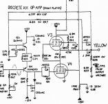
I am having problem determining what is the part on the schematic
marked VR1 and VR2 with number on it V68Z2. I believe it is a trim-pot
but I am not sure. This question would be best answered by
djmiddelkoop since he has experience with this amp. Anyone else
is welcome to help. Also, I need four 0.1mF(micro Farad) / 5000V
for this amp and if somebody has it I am willing to buy it.
Best regards!
Sasha.
P.S.
I can't wait to hear 10KVpp singing thru my ESL's.
Hello all,
I am close to finishing Acoustat SC-X3 DD tube amp from 1979.
I am having problem determining what is the part on the schematic
marked VR1 and VR2 with number on it V68Z2. I believe it is a trim-pot
but I am not sure. This question would be best answered by
djmiddelkoop since he has experience with this amp. Anyone else
is welcome to help. Also, I need four 0.1mF(micro Farad) / 5000V
for this amp and if somebody has it I am willing to buy it.
Best regards!
Sasha.
P.S.
I can't wait to hear 10KVpp singing thru my ESL's.
VR probably means Voltage Regulator
VR1 and VR2 would normally be contractions for Voltage Regulator 1 and Voltage Regulator 2. With a name like V68Z2 it sure could be a 68 Volt zener especially since 68V is a standard value for a zener. The less common symbol sometimes used for a zener diode is a little rectangular box with a streched "Z" in it usually turned sideways, it could look like a trim pot symbol.
If I'm right, your biggest problem is in detrming the correct wattage zener to use. Find the supply voltage, between that and the zeners (in series?) will be a resistor. Supply Voltage minus zener voltage divided by resitor value equals zener current. Current times zener votage equals watts; typically one would use a zener around double this wattage for margin.
One other component often called a VR is a transient suppressor like a metal oxide varistor. These also come in 68V versions. They are designed to absorb a high transient energy and have relatively loose voltage threshold accuracy i.e. they will trigger somewhere in the neighborhood of 68V.
Arc suppresion?
ESL panels are known to arc over from excessive excursion or dirt.
I would guess that VR2 is meant to protect Q3 from large voltage spikes. There is AC feedback from the panel back to the amplifier through the 4.7 pF capacitor C37. If VR2 was a zener it would kill this feedback unless the volatge divider of R57 and R56 is arranged so that the zener normally does not conduct.
Without knowing the cathode Voltage of V3, I can not calculate this.
As an arc suppresor, a standard 1/2 watt zener would be fine since R57 is 6.8 Meg. A larger zener or an MOV would probably have too much capacitance and would affect the signal from C37. Note that C37 might be there to stop the amplifier from oscillating and not for linearizing feedback.
I can help more if you know the idle state voltages or even the AC swing of the output, but I think the design is such that normally VR2 does not conduct.

Another guess:
Multi turn trim-pot for tube bias adjustment. I don't see any other
way to adjust bias in this circuit and I think bias adjustment in
tube amps is a must. Since this is only one half of the one side
of the amp it is important to adjust equal bias on both sides to
achieve minimum voltage offset on the output.
Just a guess.
Regards.
Re: Acoustat DD amp
Sasha,
You are the fellow that fixed my RPTV and got to hear the speakers in my avatar aren't you?! I remember our discussion about your efforts to make an ESL amp.
I have quite a large supply of some expensive NOS, Plastic Caps Inc. metal can oil caps rated at 0.5 uF/5 kV. Be happy to sell a few.
I think I have some dry, wound foil and plastic 0.08 uF/15,000 VDC axial caps also.
Did you get anywhere with my multi channel surround amp?
Cheers,
Rob
sasha said:Hello all,
I am close to finishing Acoustat SC-X3 DD tube amp from 1979.
I am having problem determining what is the part on the schematic
marked VR1 and VR2 with number on it V68Z2. I believe it is a trim-pot
but I am not sure. This question would be best answered by
djmiddelkoop since he has experience with this amp. Anyone else
is welcome to help. Also, I need four 0.1mF(micro Farad) / 5000V
for this amp and if somebody has it I am willing to buy it.
Best regards!
Sasha.
P.S.
I can't wait to hear 10KVpp singing thru my ESL's.
Sasha,
You are the fellow that fixed my RPTV and got to hear the speakers in my avatar aren't you?! I remember our discussion about your efforts to make an ESL amp.
I have quite a large supply of some expensive NOS, Plastic Caps Inc. metal can oil caps rated at 0.5 uF/5 kV. Be happy to sell a few.
I think I have some dry, wound foil and plastic 0.08 uF/15,000 VDC axial caps also.
Did you get anywhere with my multi channel surround amp?
Cheers,
Rob
sasha said:Hi Rob,
Yes that's me. Actually last night I found on Ebay just what I need and
very cheap too.. I have already placed the bid but if I don't' vin I will contact You. Regarding Your amp, it was bad DSP board so I stopped there and used it for parts.
Regards.
OOPs. Well you weren't supposed to do that without making an arrangement with me since I had not gifted you the amplifier, just gave it to you to evaluate and repair if practical. Perhaps you could save me the back panel that contains the half million rca receptacles. I need to make a multi source stereo audio selector for my big system downstairs.
Can you send me your phone number on PM and I'll try to call you.
Cheers,
Rob
Hi Rob,
Sorry I misunderstand agreement for Your amp.
I think You told me to fix it for cheap or use it
for parts. Anyway the rest of the amp is in garbage, but don't worry I have nice Yamaha amp for You.
It looks very nice cosmetically but it is not working so you can use it. I'll see You soon. I have your PN somewhere.
I am having problem determining what is the part on the schematic marked VR1 and VR2 with number on it V68Z2.
I believe it is a trim-pot but I am not sure. This question would be best answered by djmiddelkoop since he has experience with this amp.
Sorry for the late reply Sasha, didn't notice it before.
VR1 and VR2 are Varistors(=resistor which acts like a zener above a specified voltage) with the orginal P/N 6BZ2.
They are used for protection of Q1 and Q3.
In case you cannot source the parts, replace it with a 1N4007 diode from the Base (Anode) to the Collector (Kathode or white band on diode) of these transistors.
This will give protection also.
Hope this helps,
Dick.
Thank You so much Dick,
Now I can finalize my amp. Is there anything else important I should know about it and it is not in the schematics before I flick the switch??? Are all values in the schm. correct?
And bravo to You hermanv, You were spot on regarding this mysterious part.
Thank You all guys.
If You don't here from me soon I am probably fried by 5KV.
No problem, you're welcome.Thank You so much Dick
Yes, don't worry. The filament xformers for the upper tubes must be capable of handling 5kV isolation between primary and secondary windings.Are all values in the schm. correct?
When switching on for the first time make shure the HV is disabled and check the voltages you can.
Be shure to stay away from the tubes and surrounding parts when the HV is on.If You don't here from me soon I am probably fried by 5KV.
Try to get a HV probe for your voltmeter.
Dick.
For the 6HB5 I have good results with the GE, National and Realistic brands. I know that Sylvania will cause trouble.
I was also looking at specs of other Compactron tubes and also found the 6HV5 as a replacement candidate.
I havan't had the chance to try them yet, but I don't see why it shouldn't work.
Give it a try and please let us know.
Dick.
I was also looking at specs of other Compactron tubes and also found the 6HV5 as a replacement candidate.
I havan't had the chance to try them yet, but I don't see why it shouldn't work.
Give it a try and please let us know.
Dick.
Be very very carefull...
From the Audiostatics I've seen around (I don't know much about them frankly) it looks like a smaller speaker so probably has not as much capacitance as say a larger Martin Logan. That being said, the alternative tubes listed here just may work ok, you'll have to "experiment". Keep in mind that the 6hb5s look like they have the most current capability which is what is needed according to the Acoustat lover's society when driving multiple panels. It's sort of funny that the other tubes are rated for more power dissipation but look like they have less current capability according to the specs I see. I don't know, maybe I'm wrong. After Googling some, it doesn't look to me that specs are the strong point with some of these tubes.
As for the IN4007 being installed from base to collector, I don't believe that this approach will provide much overvoltage protection. When it does kick in, you'll be a day late and a dollar short. Look at the circuit again and just do some elementary analysis. Perhaps you'd be better off staying with the original game plan and using a suitable voltage limiting device somewhere in between 0 and 150 volts. Also, there is only one bias to each side of the circuit, and that's the variable resistor denoted as such.
I have to compliment you Sasha on your work if you indeed have built one of these beasts. If it's not too much of a secret, I for one would enjoy seeing your work along with my compliments to the chef...")
From the Audiostatics I've seen around (I don't know much about them frankly) it looks like a smaller speaker so probably has not as much capacitance as say a larger Martin Logan. That being said, the alternative tubes listed here just may work ok, you'll have to "experiment". Keep in mind that the 6hb5s look like they have the most current capability which is what is needed according to the Acoustat lover's society when driving multiple panels. It's sort of funny that the other tubes are rated for more power dissipation but look like they have less current capability according to the specs I see. I don't know, maybe I'm wrong. After Googling some, it doesn't look to me that specs are the strong point with some of these tubes.
As for the IN4007 being installed from base to collector, I don't believe that this approach will provide much overvoltage protection. When it does kick in, you'll be a day late and a dollar short. Look at the circuit again and just do some elementary analysis. Perhaps you'd be better off staying with the original game plan and using a suitable voltage limiting device somewhere in between 0 and 150 volts. Also, there is only one bias to each side of the circuit, and that's the variable resistor denoted as such.
I have to compliment you Sasha on your work if you indeed have built one of these beasts. If it's not too much of a secret, I for one would enjoy seeing your work along with my compliments to the chef...
- Status
- This old topic is closed. If you want to reopen this topic, contact a moderator using the "Report Post" button.
- Home
- Loudspeakers
- Planars & Exotics
- Tube amp specifically for driving ESLs