Probably 47 instead of 60 won't be noticable on a filter cap. You notice, on the can, there are circles, squares, triangles, or moons to tell you which section is what value. You label the wires on those terminals with tape and a sharpie marker, then you remove them. Then you install the axial caps on terminal strips with the plus's on one strip and the minus's on the other strip. Then put the named wires on the plus terminals of the right value. Then you put a black wire on both minus's, and connect it to either the wire that was on the tab of the can, the outer case, or if not one, then to the grounded leg of the terminal strip (the one with the screw through it to the metal case). Specific ground wire from the minus of the can or of the axial cap to the ring around the tube that consumes the plus current is best, but your amp may have not wired it that way, they may use the metal chassis for return.
newark.com in NC has got the 68uf 450V see this http://www.newark.com/panasonic/eeuee2w560/capacitor-alum-elec-56µf-450vdc/dp/39P9936
I can't see the farnell.com stock in Canada, the same company, the software is too smart to show it to me since I live in the US. call up www.farnell.com, click canada, click passive components, click capacitors. Then select aluminum electrolytic, and 450 VDC, stock only at lower left, then it will show in in the value column what number of lines they have at that value. Click a couple of likely values, and push "show selection" button. If you only order things in stock at farnell, they mostly stick it one box and charge you one shipping price. (Once they sent two boxes on the same day, costing me $12 shipping instead of $6. I don't pay UPS residence rate, I'm across the street from a factory).
Last edited:
I can't edit. Unplug your amp, measure everything you are going to touch at under 25 VDC, remove jewelry, discharge anything that was above 25 VDC and measure again. Put on safety glasses. Mark your wires with scotch tape & sharpie. Heat up iron and wet cleaning sponge.
Important, if the amp sort of works now, change only 1 cap at a time, then try it out and see if you made it better or worse before doing another. Worse, figure out what you did wrong or take an after picture ask us for help if it is not obvious. Better, unplug, measure & discharge, put in the next cap, you are on a roll!
Important, if the amp sort of works now, change only 1 cap at a time, then try it out and see if you made it better or worse before doing another. Worse, figure out what you did wrong or take an after picture ask us for help if it is not obvious. Better, unplug, measure & discharge, put in the next cap, you are on a roll!
CAPACITOR, 68UF, 450V, 18X40MM
Capacitor Application:General Purpose;
Dielectric Type:Aluminium Electrolytic;
Capacitance:68µF;
Capacitance Tolerance:± 20%;
Voltage Rating:450VDC;
Life Time @ Temperature:10000;
And a 20uf @ 450 VDC, (For the filter cap), atleast 2 terminal strips, a
20-20-20-20@450 can cap, a 100k 2w resistor, and an aligator jumper clip. I think that should be everything I would need, right?
The plus of both on one strip, which would be attached to the corresponding value from the can, and the minus of both caps on a separate strip, of which I would attach a black ground wire to each of them, then solder them both to the black ground wire that was attached to the old can cap. If I can follow those very simple steps, everything should work out wonderfully, right?
Sorry for being such a pain, but I really like to know exactly what's going on.
You need at least 3 terminal strips, they come in a pack of 5. There are 3 terminal versions and 5 and 6 terminal versions, you choose. You need a cap to replace the blue electrolytic you found, and I think you said something about another. All electrolytics, even the axials, if older than 1995 need to go for full power rocking. That link I gave you was a radial cap, so both the plus and minus will be on the same header on those. Axials, you mount them between two strips.
You can get clip leads from R***** S***** cheaply, and their rosin core tin/lead solder was okay the last time I bought it and comes in less than 1 pound rolls like farnell has.
At the hardware store when buying tools, they might also have Oatey #5 solder flux. If you dip old scrap wire in that, it sucks the old solder nicely off the can tabs and keeps it from splashing so much. Wash with a wet paper towel afterwards, it makes an acid.
To save freight, you might buy the 100 ohm 3 W resistor now to put in series with the rectifier line (the black thing with a line on it) to keep the current rush of full size caps from blowing it up. It goes on a header too. At hardware don't forget 5/32" drill for 6-32 screws and nuts, and a magnet to trap trash steel. I use a hand crank drill, it throws less trash around.

That is correct. You can cut 1 wire by putting both negative cap terminals on the same header terminal. You'll see when you buy them, one of the terminals continues to the bracket that is screwed to the aluminum base, which is apparently how your amp conducts the return current (ground). That is where you put the negatives. The bracket on the old 60-20 cap is the return(ground), since there is no black wire on the outside can tabs..
Last edited:
now I feel confident that I can complete this project. Thank you very much for the help, I really appreciate it. It would be very unlikely that I would find a reputable tube repairer around here, and I certainly will save some money doing it myself. Now I just have to order the terminal strips and the caps, and I'll have her up and running pronto.
I also learned a considerable amount about caps and circuits from this. Thanks!
I also learned a considerable amount about caps and circuits from this. Thanks!
I just changed 4 coupling capacitors, tested the amp, and it worked fine. I then moved to the electrolytic caps. I replaced the 68uf @63v axial with the closest thing, a 56uf @63v radial cap. I replaced a 22uf @450, then I replaced one of the multi section filter caps. I had marked everything and soldered (very amaturely) everything just how it should have been. I had to reuse the 470 ohm resistor and the 8.2 ohm resistor, because I didn't have any to replace them with. Then I powered up the amp, all the tubes lit up fine, but when I hit the standby switch, no sound or buzz whatsoever comes out of the speaker. Here are some before and after pictures to give you an idea, and maybe help me out.
68uf @63v Before

After

22uf @450 Before:

After:
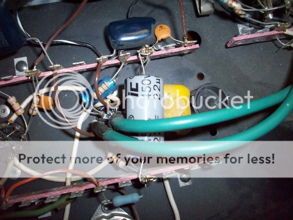
20/20/20/20 uf @450 Before:


After:


68uf @63v Before
After
22uf @450 Before:
After:
20/20/20/20 uf @450 Before:
After:
I hope it's nothing serious like a borked OT or something like that, and only something simple like bad resistors on the leads of that filter cap. Any help would be massively appreciated, I've been having trouble focusing on anything besides worrying about my amp for two days. I've even lost some sleep worrying. But mostly, I just really want some very loud music in the house.
I see you missed the advice to change one thing at a time, then ask for help if it doesn't work. We'll have to start at the very beginning. Do you have a 600 VDC meter, and a couple of clip leads? There should be a wire running from the line end of one of those black diodes to a 450 V cap. clip the leads on, turn meter to 600 VDC, then turn it on a minute, then back off. What was the voltage at that cap? The black lead (negative) should go to the frame somewhere.
I though you were going to buy individual caps. I see in after, a can still hooked up. You replaced a can with a new can?
I think I see the diode with the line going to a 120k resistor (brown red yellow). That is another place to check the B+ voltage at the very beginning.
The usual hookup is rectifier line to a cap section, then to the plates of the power transformers. Also through a resistor to another cap section, then to the plates of the grid driver tubes for the power tubes. Then though another resistor to another cap section, then to the plates of the input tubes. The voltages of the 4 sections should be something like 400,300, 250,225, depending on what actual tubes you have. You do have two big tubes (power tubes) don't you? What are they? You can look up the datasheet on triodeelectronics.com. The plate is the part that looks like a T. The plates of the two big ones may go to a transformer (OuputT) and the first high voltage cap may go to another winding of that transformer.
Last edited:
Okay, on the 68 cap at top, make sure the negative line goes to the left. On the 22 @ 450 the plus before looks like it is to the left. Make sure that + is down on the bottom. I think.
Oh, and to blow a transformer it would probably stink. With those cheap 1n4007 rectifier diodes, you might blow one of them, or maybe the end out of a cap if it is hooked up wrong. The diodes are about $.20. If One is blown you will have 500+ AC between the two non-line parts of the two diodes (use 2 clip leads) and no DC on the common lines parts. I think the lines of the diodes should be joined together in this amp, they do that inside the tube on a tube rectifier amp. If the only problem is that the inrush current of new caps is too much for the rectifiers (too loud, in other words) you can put a 100 ohm 4 W resistor on a terminal strip between the lines of the diodes and the first B+ cap.
Oh, and to blow a transformer it would probably stink. With those cheap 1n4007 rectifier diodes, you might blow one of them, or maybe the end out of a cap if it is hooked up wrong. The diodes are about $.20. If One is blown you will have 500+ AC between the two non-line parts of the two diodes (use 2 clip leads) and no DC on the common lines parts. I think the lines of the diodes should be joined together in this amp, they do that inside the tube on a tube rectifier amp. If the only problem is that the inrush current of new caps is too much for the rectifiers (too loud, in other words) you can put a 100 ohm 4 W resistor on a terminal strip between the lines of the diodes and the first B+ cap.
Last edited:
There is two filter caps, one that was easy to find, which I had just replaced, and the one that doesn't exist anymore, in which I still need to make with the terminal strips and individual caps. All the positives and negatives are correct with those two caps. My multimeter is on the fritz right now, so it'll have to all wait until I can get it working.
And as for changing them without testing, after I had changed the coupling caps, I showed my father which 'lytics is was changing for which. When I got home from work the next day, I found all the caps that I intended to replace de soldered. At least I had each cap memorized, plus pictures of them and notes.
If you're anxious to do something useful, count your tubes and write down what numbers are in each place. Then take an overall bottom picture, and label, if you have photoshop or draw on Word or something which tube is in which place. We need to trace the four HV wires from the gang cap to which tubes to figure out the schematic. Oh, one other thing. Do the tubes light up with the power on? Meaning the filaments (light bulb parts) still work?
You're in Saskatchiwan, a Sears non-autoranging meter like # 82140 is adequate for power supply study. Mine cost $29. You can't work tubes safely (measuring the voltage before touching) without one. Other than broken leads or bad battery or fuse, I can't fix a meter without a meter.
You're in Saskatchiwan, a Sears non-autoranging meter like # 82140 is adequate for power supply study. Mine cost $29. You can't work tubes safely (measuring the voltage before touching) without one. Other than broken leads or bad battery or fuse, I can't fix a meter without a meter.
Last edited:
To purchase a voltmeter that is actually useful on music as well as DC power supply problems, see this thread:http://www.diyaudio.com/forums/tubes-valves/185377-vtvm-substitute.html The flukes tend to run $150 up unless trashed, but some of the other devices mentioned might be affordable new on the internet. VTVM's are great too, but the best way to find one out here in the middle is to use searchtempest.com for "ham radio equipment" with a picture. Usually the owner doesn't let the VTVM go until he is incompetent or dead, and the heirs don't know what it is. Simpson and Triplett made them, also HP. The Heath one had variable quality depending on the builder. Any VOM from Simpson or Triplett with more than 100000 ohms per volt is also useful. 99% of them are 20000 ohms per volt, which is not useful on tubes. My Simpson 260 is the exception, it was quite useful, although broken now because I probed the wall plug on the ohms scale. A Bad practice for any meter. The meters sold in the discount stores like Meier's (here) or Hudson Bay (there probably) are 1000 ohms per volt,not good enough, and don't in fact specify anything until you buy it.
Any used meter that you buy, try it at the seller's house on the AC scale on the wall plug (120VAC) and on a fresh 1 cell battery, 1.5 regular or 1.6V alkaline on the 12 VDC or 20 VDC scale. A VTVM you would have to turn the "adjust" knob, which is normal for these old things. Some old VTVM's like the Simpson, you have to turn a switch on the probe to insert a capacitor for AC. VOM's and DVM's, it is all on the sockets and switch on the meter.
Any used meter that you buy, try it at the seller's house on the AC scale on the wall plug (120VAC) and on a fresh 1 cell battery, 1.5 regular or 1.6V alkaline on the 12 VDC or 20 VDC scale. A VTVM you would have to turn the "adjust" knob, which is normal for these old things. Some old VTVM's like the Simpson, you have to turn a switch on the probe to insert a capacitor for AC. VOM's and DVM's, it is all on the sockets and switch on the meter.
Last edited:
The multi meter just had a jammed memory button, causing the ohm scale to mess up. I just hit it on my knee to fix it. When I turn on the amp, all tubes light and heat up as per usual, and it doesn't pop any fuses.
Preamp tubes left to right: 12AU7, 12AX7, 12AX7
Power tubes: 6L6

Preamp tubes left to right: 12AU7, 12AX7, 12AX7
Power tubes: 6L6
Last edited:
Boy I wish I could edit my posts. I feel like I'm spamming for bumps. I re measured those rectifier diodes, that all read between .900v and .600v one way, except the one that goes to the power tube which reads between .6 and .9v with the correct polarity, and 1.4v with my multimeter leads on the wrong way. so would this mean that it would be drawing double that power it should, and the wrong way? (This is so fascinating to me right now)
Uh, yeah, make sure that one is 6 or 7 one way and 1999 or dash or infinity or something the backwards way (plus on the line). that's on ohms x 1000 usually, I can't get my dvm to read diodes on ohmsx100. Some meters will. You can probably get 1n4007 at R***** S***** or someplace you drive to locally, save $6 shipping. (600V PIV silicon diode, 1 amp or more). Cheapest shipping might be future.com in Vancouver, somebody said they were good.Boy I wish I could edit my posts. I feel like I'm spamming for bumps. I re measured those rectifier diodes, that all read between .900v and .600v one way, except the one that goes to the power tube which reads between .6 and .9v with the correct polarity, and 1.4v with my multimeter leads on the wrong way. so would this mean that it would be drawing double that power it should, and the wrong way? (This is so fascinating to me right now)
If you have to pay shipping, get a couple of 82 or 100 ohm 3 watt resistors to slow down the inrush on the B+, on the same order. Also extra fuses of the right size if you don't have any. Any bubbled looking brown resistors, they are probably reading high and should be replaced. The color code is Bk,Bn,Rd,Or,Yl,Gn,Bu,Vi,Gy,Wh, 0,1,2,3,4,5,6,7,8,9. The first two lines are the numbers, like 22, and the last line is the power of 10 multiplier. So red, red, brown, would be 220 ohm (mine tonight was bubbled & I don't have one.) The last line is tolerance, usually silver for 10% on something cheap like this amp.
So do you have >400V on the tab of the first cap after the line on the two diodes?
Figure out which tube connects to the input, that will be the lowest voltage on the 4 gang cap with the most resistors. The two 6L6s will connect to the highest voltage on the 4 gang cap, but their plates probably connect through a transformer to the highest voltage section of the B+ cap, the one nearest the two diodes.
Here is a schematic of an amp somewhat like yours, http://www.freeinfosociety.com/electronics/schemview.php?id=2338 The pin numbers will be different, and this amp uses pentodes (4 grids) instead of triodes, and you have the input in one tube (probably the 12AU7) and the power tube predrivers in two other tubes (probably the 12AX7). One section of the predriver will be a "phase splitter" that has big resistors in both the plate and and the cathode pins (the cathode end is the one attached to the bridge thing meaning the heater). Most of the rest of the tubes will have 1K or something to ground on the cathode end.
Last edited:
- Status
- This old topic is closed. If you want to reopen this topic, contact a moderator using the "Report Post" button.
- Home
- Live Sound
- Instruments and Amps
- Tube amp help!