SY,
I don't have power supply to generate the voltages required other than the GG itself.
JojoD818,
I've checked and checked and checked all connection points but didn't find anything wrong. I even printed out the 2 transistors spec from Fairchild to made sure that I didn't make any assumption on the leg config.
Since the 2 led are blinking, does it has anything to do with the cap C6 at the bottom of the GG schmatics?
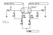
I didn't read any post about putting this CCS into a GG. But somebody did put another CCS using tube for GG (attached) in exactly the same position. Hope somebody can spot my mistake with this info.
I don't have power supply to generate the voltages required other than the GG itself.
JojoD818,
I've checked and checked and checked all connection points but didn't find anything wrong. I even printed out the 2 transistors spec from Fairchild to made sure that I didn't make any assumption on the leg config.
Since the 2 led are blinking, does it has anything to do with the cap C6 at the bottom of the GG schmatics?
I didn't read any post about putting this CCS into a GG. But somebody did put another CCS using tube for GG (attached) in exactly the same position. Hope somebody can spot my mistake with this info.
Attachments
I don't have power supply to generate the voltages required other than the GG itself.
Well, use that, then. Pull the tube and connect a dummy load resistor from the top of the CCS to the B+.
senderj,
calibrate your ccs first like SY's recommendation, you maybe pulling out too much current.
SY,
when I calibrate for say, 8mA on a ccs as plate load, I have 160V across the dummy load which means I have 8mA flowing. But when I replace the load with a tube, I end up having 180V or so on the plates. Should there be a difference on voltage or it's just that the ccs is adjusting to maintain a current of 8mA? Therefore doing what it's suppose to do.
The best way to test any sub-circuit is in the proper circuit. To be honest, I never worry too much about the exact current sunk by the CCS, I worry about the anode voltage of the circuit and adjust the CCS to set the anode voltage to allow maximum undistorted signal swing.

EC8010 said:The best way to test any sub-circuit is in the proper circuit. To be honest, I never worry too much about the exact current sunk by the CCS, I worry about the anode voltage of the circuit and adjust the CCS to set the anode voltage to allow maximum undistorted signal swing.
In that case, all I have to do is make some adjustments. Thank goodness for that trimmer.

I think jojod is close...
I was actually a lot closer... almost dead on target when I followed the master equations for the ccs, it was just that these pair of hands can't have enough.
The dummy represents the load from the tubes. With the tubes removed, connect the dummy from the CCS collector (i.e., sink point) to the B+. Calculate the resistor from Ohm's Law to give you something around 0-10V at the CCS. Whatever your desired set current is for both tubes, call it I. Whatever the B+ is, call it V. So the dummy load is R = V/I. (The power dissipated is IV, so check that your resistor is big enough).
If all is working well in the CCS, the LED will glow steadily and the drop across the dummy load will be V. If not, you've traced the problem to something in the CCS wiring or components.
If all is working well in the CCS, the LED will glow steadily and the drop across the dummy load will be V. If not, you've traced the problem to something in the CCS wiring or components.
SY,
Thanks for the reply. I've tried the dummy load today but I found that I have to change R2 to >5K to make a 4mA current on the load. However, when I put the ccs back to the amp, the current is too low. Then I adjust the R2 again to 850 Ohms to keep the current.
I then put up another ccs for the other channel. When I use ccs on only one channel (the other still use the 51k cathode R), I can have 4mA although the cathode became -20V instead of +2.5V. But when I use ccs in both channels, the current kicks high (and immediately drops back) every 2-3 seconds with the LEDs blinking just like a christmas tree. Anybody know what is happening?
Still failing.
SY,
I've posted the whole schematic before in this thread. I put the link here again.
http://www.diyaudio.com/forums/attachment.php?s=&postid=947962&stamp=1151220924
The only difference is that R2 is replaced by a trimmer and I obtained 4mA current when the trimmer is 850 Ohms. Can you spot any mistakes here?
First, check that your transistors are still silicon and have not transformed to carbon. If they're OK, double the value of the 39k reference feed resistor and bring it to your B+ (assuming it can handle the extra 5mA current) instead of 0V. That may help with PS modulation that anatech points out.
You've got something miswired, misread resistor values, and some dead transistors. With a 400V differential, a 68k feed resistor will cause about 5.5-6mA to flow in the reference string, which is perfectly safe for the leds.
Start from the beginning and put the cathode resistors back the way they were. Now just wire up the reference string and make sure everything lights up OK and doesn't flash. If you get to that point, using fresh transistors, where you've double-checked the pinout, wire the CCS back up. If initially you see the LEDs flashing with signal, you've wired to the wrong points.
I have a feeling that in the beginning, you got a transistor pinout wrong and everything has cascaded from there.
Thanks for the reply again. Not able to do it during weekdays, so will try your suggestion this Saturday.
I have checked several times to make sure the pinout are connected correctly. I check against the spec from Fairchild. I check the pinout of the transistors with the textbook on destinguishing C, B and E of a transistors. If there is a mistake on pinout connection, I should have located it.
One thing I don't understand and may be related is that, LED blinking only happens when I connect 2 ccs. LED didn't blink if I only connect 1 ccs (and the other channel still use the 51K cathode resistor). Does this symptom reveal the mistake I made in the circuit?
- Status
- This old topic is closed. If you want to reopen this topic, contact a moderator using the "Report Post" button.
- Home
- Amplifiers
- Tubes / Valves
- Tube Amp CCS?