Hi keantoken,
You're right that this will involve capacitors also. This is because the input of the sound card has capacitance, as do the cables. This will create a low pass filter. A capacitor in parallel with the dropping resistor will correct the loss of highs in the same way an oscilloscope probe is adjusted. Look oscilloscope probes up on the internet to get the concept.
Your idea of using a 7.5 ohm dropping resistor and a 0.5 ohm sensing resistor will work for a range of voltage levels. I was thinking more along the lines of an 8 ohm load resistor (or 4 ohms if you like). The "probe" would then be a higher resistance element. The input impedance of most sound cards seems to be around 10 K very approximately with some value of capacitance. The cable running to and from the sound card will add it's own capacitance to the total load.
-Chris
My sound card is a Creative SoundBlaster AWE64 Gold. I know that it is old, but it still sounds very good and has very good frequency response. I recently installed a newer and more generic (or less distinguished) soundblaster but it doesn't look that impressive. I will test both with RMAA and see what the difference is. My current sound card has RCA phono outputs, and I have an RCA to headphone converter. I was wondering if the line-in impedance is the same as the phono impedance. If I used this cable to test my sound card with RMAA, would it do anything harmful?
I didn't think about cable capacitances... Haven't had much experience with probes and cables so it slipped my mind...
Do I ever sound like I know everything that people tell me, when in reality it looks like I know nothing and I am just trying to make everybody think that I do? I have gathered an uncanny amount of knowledge through the years, but my lack of experience makes it hard to recall the things that I have read. Then when someone tells me about these things I finally remember... It's horrible...
Okay, got that model. Turns out there is very little difference between the FFT's now *sigh*. My imbalance was 2% too... Did anyone know that you can write wave (sound) files with LTSpice? You can save the output of an amp to a wave file and analyze it or listen to it later. Look up .wav in the help file or PDF. Could I use this with RMAA to get an accurate distortion figure, so that I can accurately find out if my idea works?
This is a pretty cool feature...
This is a pretty cool feature...
Keantoken, you really should not care much about 2% unbalance, unless you match also all resistors and bjts <1% in real world.
Additionally, these 2% will be swamped out by thermal variations.
Are you sure you have checked things correctly ? I get a 30% unbalance using 200ohm for one of the 150ohm.
Try the wilson current mirror, as shown in the "symasym - the sequel" thread. It will reduce unbalance below 0.1%. (openloop only, it will keep unbalanced to compensate DC-offsets via nfb, unless you tightly match the drivers)
Chris, within audio bandwidth there should be no need to compensate the voltage divider. Simply use not too high resistances. Using 1K to 100ohm for example gives a divider of 1:11 with an outputimpedance of 100ohms. The 1k will dissipate ~60mw to give output of 1v peak.
Keantoken, you would simply put this divider in paralell to the 8ohm dummyload.
Mike
keantoken,
Spice is a pretty good simulator, but you will have to build up the knowledge of distinguishing between what it tells you and what the real-world circuit will do. Just keep in mind it is just a tool, and a good one for developing, however ultimately it's still the physical circuit on the bench (and iterations of it) that will really count... Bob Pease of NS totally hates these simulators...
Cheers
Hi MikeB,
I think Chris prefers the higher impedance voltage dividers for the sound card to ensure that the audio card never gets too high a current into its inputs - even if some mistake is made (i.e. the bottom resistor of the divider wasn't properly grounded, or someone plugs in the RCA jacks with the amp turned on)...
Cheers!
clem
anatech said:I must say that it's getting scary how you can figure out my motives!
Hi Chris,
Hehe, don't worry about it, this one wasn't too hard. Remember I'm at a uni, too many kids blowing up things here... !!
")
Cheers,
Clem
Should I wait until there is a final cascoded symasym to build my amp? I am looking for the best quality I can get and the cascoded thing looks promising, however unqualified I may be to make that gesture. Anatech, think it would be useful to have a sticky or whatever which gathers knowledge about all these things like the "darlington pair" and the "wilson current mirror" and the "long tailed pair" for reference? I think that this would greatly benefit the DIYAudio community. Although I am not experienced enough to mess around with anything like that, I think that it is a good idea. I suppose that line-in impedance isn't the same as video output impedance, is it? Would I need an impedance matching network to test my card with RMAA?
keantoken, i don't think that you need to wait for cascoded version, symasym is quite good as it is (except the board layout).
The cascoded version is more like an experiment, no idea what the result will be. With the actual board layout, distortions seem to be completely dominated by somehow induced half waves from the supply rails.
Mike
The cascoded version is more like an experiment, no idea what the result will be. With the actual board layout, distortions seem to be completely dominated by somehow induced half waves from the supply rails.
Mike
Hi keantoken,
I agree with Mike. The Symasym as it sits right now is very, very good. Mike and Pavel have done an excellent job thus far. I want to make sure the community assists Mike and Pavel, rather than make things more difficult.
So build the Symasym 5.3 and be happy. You stand a far greater chance of messing up the performance with the chassis and wiring. That's how good it is. Good back to the original thread and look at pictures when it comes time to put it together.
As Mike pointed out, this next bit of chattering is entirely experimental. There is every possibility that it will perform much worse than the 5.3. It is an experiment, proof of concept. I expect the board to be reworked quite a bit.
Hey Clem,
Start clicking away! If nothing else you can blackmail ex-students later! KIDDING!
-Chris
I agree with Mike. The Symasym as it sits right now is very, very good. Mike and Pavel have done an excellent job thus far. I want to make sure the community assists Mike and Pavel, rather than make things more difficult.
So build the Symasym 5.3 and be happy. You stand a far greater chance of messing up the performance with the chassis and wiring. That's how good it is. Good back to the original thread and look at pictures when it comes time to put it together.
As Mike pointed out, this next bit of chattering is entirely experimental. There is every possibility that it will perform much worse than the 5.3. It is an experiment, proof of concept. I expect the board to be reworked quite a bit.
Hey Clem,
Start clicking away! If nothing else you can blackmail ex-students later!
KIDDING!-Chris
I succeed to obtain 0.3-0.4mv offset, matching k170-bl JFETs in less than 0.5% D-S current.
The same peers of two symasym amplifiers, with MPSA18 in input diff amp, have 3.5-4mv offset (hfe matched in less than 1%).
How is that possible?
I have 15034/35 as drivers and mjw0281/0302 as finals. I will put pictures in original thread as soon as possible.
On more word, the sound is explendid and Mike is a elctro-genius 

The same peers of two symasym amplifiers, with MPSA18 in input diff amp, have 3.5-4mv offset (hfe matched in less than 1%).
How is that possible?
I have 15034/35 as drivers and mjw0281/0302 as finals. I will put pictures in original thread as soon as possible.
On more word, the sound is explendid
and Mike is a elctro-genius Hi roender, thats really weird... I had 2mv with the sk170 (matched to ~1%). 3.6mv is the standard offset using mpsa18. Maybe you had some cancelling ?
I am quite convinced that the "dc-offset" is caused by thermal unbalanced current mirror.
Looking forward to your pics and listening impressions...
Mike
I am quite convinced that the "dc-offset" is caused by thermal unbalanced current mirror.
Looking forward to your pics and listening impressions...
Mike
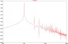
Okay, next thing. This is another thing that I have noticed about symasym which I think could lessen the even harmonics if dealt with properly. I have noticed a .76% imbalance in the Ib of the MJE15034/35 (I am using these), where the MJE15034 has more current than the other (142.3uA : 108.5uA). I have also noticed some even harmonics (I have the FFT in my attachment if there is something wrong) not immediately after the fundamental but the 2nd even harmonic is still noticeable (visually) And I think that correcting this imbalance would lower the distortion not a large amount, but significantly. Is there any sort of anything that would help balance these? I am just telling what I am seeing, and not really trying to correct it myself, but just politely notifying the creators of these things in hopes that I could aid in the development of the cool symasym. That would be cool
Just trying to feel significant
godspeed, mike!
PS: I am now using the wilson current mirror
This FFT was taken with 8ohm/5.26mW@1kHz
symasym. That would be cool Just trying to feel significant
godspeed, mike!
PS: I am now using the wilson current mirror
This FFT was taken with 8ohm/5.26mW@1kHz
Attachments
MikeB said:Hi roender, thats really weird... I had 2mv with the sk170 (matched to ~1%). 3.6mv is the standard offset using mpsa18. Maybe you had some cancelling ?
I am quite convinced that the "dc-offset" is caused by thermal unbalanced current mirror.
Looking forward to your pics and listening impressions...
Mike
Hi Mike, I have all peers matched in less than 1% and thermally coupled. In fact, the offset oscillate between -0.3 and +04mv.
Roender, if the dc-offet changes between -0.3mv and +0.4mv, i see no reason to worry. Or is it +4mv ?
Keantoken, your mismatch between base currents can be fixed in real world by matching these devices.
About your FFT, something is very wrong, it shows a THD of ~1%, and way too much high order harmonics. Have you verified that bias in outputstage is ~50ma ? You might have severe cross over distortion.
At these levels you should have ~0.001% thd, ~-100db of 2nd harmonic relative to the signal.
Mike
- Status
- This old topic is closed. If you want to reopen this topic, contact a moderator using the "Report Post" button.
- Home
- Amplifiers
- Solid State
- Troubleshooting your Symasym