That's the first thing that I tested even when their color codes are correct. The four resistors forming the THINGY have their respective measured values, 2x100k, 36k and 30k.It's possible that one of the resistors is the incorrect value (it happens!).
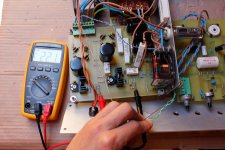
This morning I did what you asked me to do: remove the MPSA42 from the THINGY and hook directly the supply to the potential divider formed by 36k and 100k resistors. There is almost no change: the voltage at B+ is like 242 Volts and the voltage at the 100k resistor is about 23 Volts (oscillating), more or less the same as with MPSA42. I have a spare EZ81 and I repeated the tests with that. No changes but when I turned the HT supply on (rectifier filament pre-heated more than 1 minute at about 4 Volts AC) I could hear some crispy sounds (quietly) but I thing that could be due to gass residues inside the bulb.
That's it, the emitter follower is then working properly. I don't remember if I told you that it perfectly worked once on Saturday morning (the elevated supply was elevated like 250 Volts, was able to give 6.3 Volts and the non elevated supply was perfectly symmetrical). I think I forgot to say that when HT is turned on B+ is at about 240 Volts instead of the 340 Volts that I get when either disconnecting the elevated supply from the THINGY or when disconnecting the non elevated supply from ground.
When I say "oscillating" I mean that voltages in the potential divider are slowly time varying: 22.8 - 22.9 - 23 - 22.2 - 21 - 20.6 - ...
When I say "oscillating" I mean that voltages in the potential divider are slowly time varying: 22.8 - 22.9 - 23 - 22.2 - 21 - 20.6 - ...
The B+ voltage tends to descrease very slowly, maybe 1 Volt every 10 seconds. The upper resistor is 36k, so the voltage drop there is about 220 Volts. That implies that is dissipating about 1.34 Watts. I wonder why the upper resistor is still alive because it is rated to dissipate only 0.6 Watts, perhaps it's because I leave the HT turned on only for a few seconds. The lower 100k resistors are rated at 3 Watts.
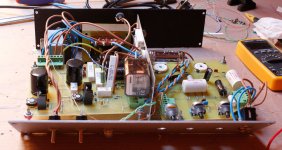
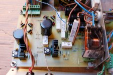
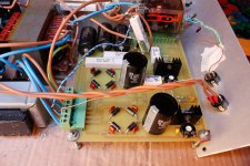
I attach some photos that I took the other day. Sorry for the shoddy work with dropping resistors from rectifier filament but I lacked of space on PCB")
I attach some photos that I took the other day. Sorry for the shoddy work with dropping resistors from rectifier filament but I lacked of space on PCB
Attachments
I verified the resistors and are ok, their measured resistance value is perfect. I've just disconnected the elevated supply from the THINGY and voltages are perfect, so the problem definitely is not in the THINGY. The signal path PCB is not connected when testing so the problem can't be there. My thought was as previously stated: there is somekind of interconnection between the LT supplies. Because the non elevated supply is grounded there exists a path to ground that affects the THINGY voltages. I think that the only element that can be causing this is a relay. Maybe a leakage/coupling between its poles. Do you think that the relays that I used (http://www.findernet.com/comuni/pdf/S30EN.pdf) are able to operate either 1 A AC or 250 Volts DC?
Sorry for being such a drag but I am hopeless
Sorry for being such a drag but I am hopeless
Well, just disconnect the relays and see if that fixes things. You can temporarily hard-wire the power connections their contacts make. For test purposes only, you should have those power connections physically off the relay terminals- but insulate them and be super careful.
I have the pleasure to confirm that the relay switching the 750 Ohms resistors is causing the problem. It works switching off the 750 resistor to set up the on mode, so to test the supplies I just take it off. Everything perfect. This relay is not able to operate at those voltages, I need to get one that can deal with them. I had never worked with relays. Thanks SY for your attention.

- Status
- This old topic is closed. If you want to reopen this topic, contact a moderator using the "Report Post" button.
- Home
- Amplifiers
- Tubes / Valves
- Troubles when elevating a LT supply