Hi, I am exploring bjt buffer output stage using MicroCap. There is a problem (at least in simulation) when output is cap-loaded. Input of the driver is loaded with +/-30V 10KHz rise and fall time 100nS.
I attached the schematic and output signal when loaded with 100nF and 2uF. (I used MJL model by Andy C)
Is this simulation problem real and could this be fixed without using output coil ,zobel and feedback?
Thanks.
Borko.
I attached the schematic and output signal when loaded with 100nF and 2uF. (I used MJL model by Andy C)
Is this simulation problem real and could this be fixed without using output coil ,zobel and feedback?
Thanks.
Borko.
bogdan_borko said:2uF-8-Ohm-load:
hi Bogdan,
send me your .cir and I will play with it as well. I use MC9. My e-mail is nico_ras@telkomsa.net
Nico
Nico Ras said:
hi Bogdan,
send me your .cir and I will play with it as well. I use MC9. My e-mail is nico_ras@telkomsa.net
Nico
The file i sent.
Cheers!
I have not seen this in practice on a square wave.
However, on a number of amps I've designed and built, on a10-15Khz sine wave output, I got 'ringing' at 100Khz and higher on the final 90 degree quadrant (so as the sine wave comes off the negative pk voltage and heads towards 0V.
In these cases the cause is almost always parasitic oscillation in the output stage. Additionally, if your amp has a 'sticky' problem, this can make the situation worse on output voltages that swing close to the rails, but don't quite clip. ('sticky is when the amp sticks to the rails when overdriven - i.e does not recover cleanly)
A few things to fix it:-
1. Use a Zobel directly on the output before the output inductor (10Ohms + 0.1uF)
2. Use a 100 Ohm in series with the pre-driver base transistors from the VAS
3. In really stubborn cases, I use a 27 ohm in series with the the positive driver base and the negative driver base. From each driver base, I put 1nF 1kV capacitor to 0V.
Parasitic oscillation in triples is a common problem - in fact, Microcap even published an ap note on this issue and how to cure it (sorry, I do not have it anymore) - this is where I got the 27 ohm and 1nF cap solution from (they used different values - I got mine from trying it practically).
Good luck
")
lineup said:Bonsai
Why settle for Tripple
When you can try the brand new
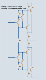
Lineup Quattro Output Stage
.. just invented
high gain super plus!!!!
Hi Lineup.
Very interesting "invention", I would like to try this. Have time to kill.
Nico
lineup said:Bonsai
Why settle for Tripple
When you can try the brand new
Lineup Quattro Output Stage
.. just invented
high gain super plus!!!!
NOPE
 got to think this one through a little.
lineup said:
Lineup Quattro Output Stage
.. just invented
high gain super plus!!!!
Looks a lot like the Bryston Quad-complementary.
bogdan_borko said:Is this simulation problem real and could this be fixed without using output coil ,zobel and feedback?
Thanks.
Borko.
These outputs are usually quite stable, even without a zobel. Try getting rid of C4. With that cap, you can end up with switchoff problems. Every time I've used one in that position, I ended up getting rid of it because I didn't like the behavior at clipping.
lineup said:Bonsai
Why settle for Tripple
When you can try the brand new
Lineup Quattro Output Stage
.. just invented
high gain super plus!!!!
No feedback allowed...
bogdan_borko said:
No feedback allowed...
If no feedback is allowed, then technically you have to exclude darlingtons (double, triple, or even quad) as well.
In these cases the cause is almost always parasitic oscillation in the output stage
Yes ,I figured out that this is the problem source...
Attachments
bogdan_borko said:
Yes ,I figured out that this is the problem source...
I find that your circuit thermally it is not stable.
Put source 0V amplitude and then run transient with temperature setting 27,50 Now look at the current through emitter resistors.
You can also see this with V(OUT) at 27 deg, offset is a few millivolt, but at 50 degrees it is 10V
Regards
Nico
Nico Ras said:
I find that your circuit thermally it is not stable.
Put source 0V amplitude and then run transient with temperature setting 27,50 Now look at the current through emitter resistors.
You can also see this with V(OUT) at 27 deg, offset is a few millivolt, but at 50 degrees it is 10V
Regards
Nico
Well it`s just an example but thanks, I didn`t knew the trick.
What about the main problem?
bogdan_borko said:
Well it`s just an example but thanks, I didn`t knew the trick.
What about the main problem?
I used the pulse stimulus and I do not see the oscillations you do, in fact the wave has a small over and undershoot. I am not sure for the reason C3, I used 1-10n or so between individual bases. In practice, obviously you will be applying NFB when used in circuit.
I do not have the same models as you since your models was not in the model page. I do not see the oscillations that you do.
We use a lot of On-Semi products and when I saw the comments that their models are unreliable, I contacted their support engineers and they assured me that there models are based on worst case scenario.
I was told that if I want to create models for individual transistors I can do it but that am making a big mistake. So I use their models as provided.
I hope I was of some help,
Nico
- Status
- This old topic is closed. If you want to reopen this topic, contact a moderator using the "Report Post" button.
- Home
- Amplifiers
- Solid State
- Triple emmiter follower