For the discussion I did not want grid positive A2 operation, which would confuse everything.
DT
Then don't talk about bias and operation modus, has nothing to do with the principles of feedback. Keep it to the signal!
Jan
Feedback is a circuit technique that can be applied to ANY circuit. The available literature gives masses of info how the limits of input impedance/current, gain, etc impact on the final result. A full treatise even includes forward propagation of the input signal through the feedback network to the output!
Saying that there is a physical limit to a circuit technique is barking nonsense.
It is true that the numbers and results from applying feedback to tubes are different from applying it to solid state or opamps, of course they are.
But the principles are always the same, the equations are the same, and the outcome is different because the input to the equations is different.
Jan
PS maybe a little tip: if you feel that Bill Waslo doesn't know what he is talking about, it must be because you are new here. Tsk tsk!
You may wish to work on your own credibility first. So far you're not making a whole lot of sense.
Jan, I have to tell you that I think Dual Triode wandered into a land mine here that really was not his fault. He just did not know the history of the commenters at the Lounge. You, among others, are well known to many of us. I cannot speak for others but I know I have an instinctive distaste for you and many of the others there that mask their prejudices behind a faux "measurement" objectivity. The real problem is that I do not enjoy your disrespect and sullen arrogance towards open minded genuinely creative people such as John Curl. Maybe you could spend all your time there where the negativity really can't be worsened. I just knew when I saw this subject on the Tube section that you and yours were going to try to imply that feedback can be applied perfectly in current amplifiers. It can't and you know it. It has nothing whatever to do with equations being wrong. You know that that is NOT what I was implying. Its the usual motus operande of trying to define what somebody has said in a way that you know they did not intend to win an argument. It's cheap and dishonest.
I should also add that if you and others are in the least bit alarmed that I am on a hair trigger then you should know its because I read what you say in other threads against people who make perfectly valid arguments and suggestions. It really is nothing more than a bullying mentality. Own it and quit acting like a victim when the same thing comes back on you. Don't whine.
Last edited:
This thread is supposed to be about feedback and triodes. Could those who wish to argue about something else start their own thread? Then they can pool their ignorance or wisdom (as appropriate) without bothering us here. We may wish to join them in that thread.
Whether we use the 'voltage amplifier' or the 'transconductance amplifier' model of the triode we can discuss how feedback works. That is what we were trying to do in this thread; hopefully helping DualTriode gain some understanding. Others may watch and learn too.
Nothing can be done perfectly in the real world. Many things can be with a sufficiently good approximation to perfection in the real world that a theoretically perfect model can help us understand what is happening. If this were not true, much of engineering would be impossible. Attacking people for what you think they are about to say is not a helpful way of having a discussion.exeric said:I just knew when I saw this subject on the Tube section that you and yours were going to try to imply that feedback can be applied perfectly in current amplifiers.
Whether we use the 'voltage amplifier' or the 'transconductance amplifier' model of the triode we can discuss how feedback works. That is what we were trying to do in this thread; hopefully helping DualTriode gain some understanding. Others may watch and learn too.
Jan, I have to tell you that I think Dual Triode wandered into a land mine here that really was not his fault. He just did not know the history of the commenters at the Lounge. You, among others, are well known to many of us. I cannot speak for others but I know I have an instinctive distaste for you and many of the others there that mask their prejudices behind a faux "measurement" objectivity. The real problem is that I do not enjoy your disrespect and sullen arrogance towards open minded genuinely creative people such as John Curl. Maybe you could spend all your time there where the negativity really can't be worsened. I just knew when I saw this subject on the Tube section that you and yours were going to try to imply that feedback can be applied perfectly in current amplifiers. It can't and you know it. It has nothing whatever to do with equations being wrong. You know that that is NOT what I was implying. Its the usual motus operande of trying to define what somebody has said in a way that you know they did not intend to win an argument. It's cheap and dishonest.
I should also add that if you and others are in the least bit alarmed that I am on a hair trigger then you should know its because I read what you say in other threads against people who make perfectly valid arguments and suggestions. It really is nothing more than a bullying mentality. Own it and quit acting like a victim when the same thing comes back on you. Don't whine.
Wow....
I've seen often that people run out of tech arguments in a discussion and resort to personal attacks and insults and such in a desperate attempt to salvage their case, but already after two posts, that's a first.
But I don't think there is a lot of common ground for discussion anyway with someone who believes JC is 'open minded genuinely creative people' (and for the record I do respect John a lot for his accomplishments).
Jan
 exeric the only person setting land mines here is your self. I have not deleted your post (though I almost did).... I think it serves more purpose to leave it here so that this warning has context.
 Don't you mean to CREATE their instrument's characteristic sound? Because an electric guitar, when you're listening only to the strings, doesn't even vaguely resemble the sound from the tube amp's speaker! (A former guitarist here, BTW). The amp is a creative instrument, not a accurate reproducer.
This, this, so much this. And it may not be coincidence that the guy I know who knows the technical ins and outs of guitar amps and pickups the best is also one of the very best guitarists I've ever heard. Feedback is a tool he uses as well, since it drastically changes the way an amp overloads and can be tailored to get effects related to blocking and squegging (exactly the opposite of what we do for hifi).
OK, back to topic...
I see one triode input and two triode outputs.
Hello All,
I want to talk about triode outputs today.
First off I want to say, I know that this is all vanity, in some sense this has all been done before. To everything, turn,turn, there is a season, turn turn turn.
Look at the figures attached below as you read along.
If there is no voltage divider there is no output. Even for op-amps if there is no voltage divider there is no output. To see the op-amp voltage dividers clink on the link in post # 5 to see the circuit of a discrete JFET op-amp circuit. In the case of the triode the voltage divider resistors are outside the vacuum envelope.
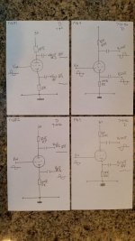
For clarity there are no external loads in the 4 figures attached. Input is applied between the grid and the common node. B+ is applied at the top of the figure. Common is at the bottom. As resistors are added to the figures B+ voltage is increased keep maintain consistent idle current.
Figure 1
With signal voltage applied to Vin there is current modulation through the circuit. Because there are no voltage dividers at the Anode or cathode there is no voltage modulation. The anode remains at B+ and the cathode remains at 0 volts. Short version, no output and no feedback.
Figure 2
Rp is 500 ohms; there is voltage output at Vout1. Rp remains 0 ohms; there is no voltage output at Vout2. Short version there is voltage output and feedback at Vout1. There is no output or feedback at Vout2
Figure 3
Rp is 20K ohms; there is voltage output at Vout2. Rk is 0 ohms, there is no voltage output at Vout1. Short version there is voltage output and feedback at Vout2. There is no output or feedback at Vout1
Figure 4
Short version there is output at both Vout1 and output at Vout2. There is freedback at both Vout1 and Vout2
Summary and looking forward:
I see one triode input and two triode outputs. The outputs are measurable. I do not see physical wires looping either of the outputs to the input to form feedback loops. There is much of the intuitive part that requires bench testing.
DT
Back to the party!
Hello All,
I want to talk about triode outputs today.
First off I want to say, I know that this is all vanity, in some sense this has all been done before. To everything, turn,turn, there is a season, turn turn turn.
Look at the figures attached below as you read along.
If there is no voltage divider there is no output. Even for op-amps if there is no voltage divider there is no output. To see the op-amp voltage dividers clink on the link in post # 5 to see the circuit of a discrete JFET op-amp circuit. In the case of the triode the voltage divider resistors are outside the vacuum envelope.
For clarity there are no external loads in the 4 figures attached. Input is applied between the grid and the common node. B+ is applied at the top of the figure. Common is at the bottom. As resistors are added to the figures B+ voltage is increased keep maintain consistent idle current.
Figure 1
With signal voltage applied to Vin there is current modulation through the circuit. Because there are no voltage dividers at the Anode or cathode there is no voltage modulation. The anode remains at B+ and the cathode remains at 0 volts. Short version, no output and no feedback.
Figure 2
Rp is 500 ohms; there is voltage output at Vout1. Rp remains 0 ohms; there is no voltage output at Vout2. Short version there is voltage output and feedback at Vout1. There is no output or feedback at Vout2
Figure 3
Rp is 20K ohms; there is voltage output at Vout2. Rk is 0 ohms, there is no voltage output at Vout1. Short version there is voltage output and feedback at Vout2. There is no output or feedback at Vout1
Figure 4
Short version there is output at both Vout1 and output at Vout2. There is freedback at both Vout1 and Vout2
Summary and looking forward:
I see one triode input and two triode outputs. The outputs are measurable. I do not see physical wires looping either of the outputs to the input to form feedback loops. There is much of the intuitive part that requires bench testing.
DT
Back to the party!
Attachments
OK, so you still don't understand how the circuit works. It may be that you don't understand how any circuit works. It is difficult to know how best to help you, as you seem to bat away any attempts at correction of your wrong ideas.DualTriode said:I see one triode input and two triode outputs. The outputs are measurable. I do not see physical wires looping either of the outputs to the input to form feedback loops.
There is no value in repeating myself, so I will simply urge you to go back and read what I, Jan and others have said in this thread. Your aim should not be to criticise or disagree with us, but to understand and accept what we say.
Let me nudge you along gently.
Doctor Dave,
Let me nudge you along gently.
The theory that we are building to fit the triode is a complete hypothetical construct. This theory will take the feedback that is physically/electrically active at the anode or cathode and treat it as if that feedback is applied between the grid and common.
This theory is hypothetical the same way the noise theory in triodes is hypothetical.
The multiple types of noise generated in the triode are placed into a formula that results in a number, a voltage, if applied to the input of the model would result in the measured noise at the output. This equivalent voltage, Ein, is nowhere to be measured in the real circuit.
Now back to the triode feedback model, if you will. Let us place a resistor inline between the B+ voltage and the anode and measure the output voltage between the cathode and cathode resistor. We know empirically that adding the anode resistor will reduce the output voltage gain. This reduction in gain is caused by feedback.
When signal is applied to the circuit there is modulation of current through the circuit. This modulation of current causes a modulating voltage drop across the anode resistor. This modulating voltage at the anode is real physical/electrical input to the anode, aka plate, of the triode. This is the real feedback mechanism.
We know by definition that the grid is mu times more sensitive to input than the plate. For a 12AT7 the mu is ~ 60. Now we are ready to draw the equivalent feedback loop from the anode to the signal input. The feedback loop will include a math block that converts the deltaV at the anode to an equivalent deltaV at the signal input. Say the DeltaV at the anode is 6 volts, mu is ~60, so -(DV/mu ) is the math block, the equivalent effect at the signal input is –(6/60) or -0.1 volts.
DT
Last edited:
Sorry, you seem to have been misinformed. We are not building anything. We are trying to get you to understand things you seem not to understand at present.DualTriode said:The theory that we are building to fit the triode is a complete hypothetical construct.
If there is no voltage divider there is no output.
DT
Back to the party!
Your use of 'voltage divider' is confusing. Ohms law says that it you have a varying current through a resistor, you have voltage across the resistor. V = R * I. Make the R = 0 and V > 0. Simple as that.
I see one triode input and two triode outputs. The outputs are measurable. I do not see physical wires looping either of the outputs to the input to form feedback loops.
I do. I see a thick wire directly connecting the cathode output to the cathode input. 100% feedback, remember? ;-)
Jan
Sorry, you seem to have been misinformed. We are not building anything. We are trying to get you to understand things you seem not to understand at present.
Doctor Dave,
Thank you for your persistence or should I say patience in straightening me out.
Jerald Graeme adapted Black’s feedback theory to op-amps. Graeme used the concept of feedforward to include the inverting op-amp output into a generalized feedback model.
In this thread it is my intention to adapt Graeme’s generalized feedback model to triodes. In a sense this is building something. The model will include feedback loops and feedforward loops with the math blocks to make the model match real world measured performance.
The model including math blocks will require some intuition and real world construct validation.
DT
Explain to me how Black's feedback theory needed adapting for opamps. Then explain how that needs adapting for triodes.
At present this thread appears to be one of those "I don't understand it, therefore it is not understood" ones. I hope it doesn't turn into "I have just understood this so now I will write a tutorial article to enlighten others".
At present this thread appears to be one of those "I don't understand it, therefore it is not understood" ones. I hope it doesn't turn into "I have just understood this so now I will write a tutorial article to enlighten others".
Your use of 'voltage divider' is confusing. Ohms law says that it you have a varying current through a resistor, you have voltage across the resistor. V = R * I. Make the R = 0 and V > 0. Simple as that.
Okay; Dv = R * I, if R = 0 then Dv = 0,
Perhaps any confusion can be cleaned up in the language as we proceed.
I do. I see a thick wire directly connecting the cathode output to the cathode input. 100% feedback, remember? ;-)
Jan
Some intuition is required, then field verification. I will go to the bench and connect a hook up wire from cathode to grid and see if there is any change.
In any case the feedback model will show a feedback loop, including a math block, from cathode to the summing node.
DT
Explain to me how Black's feedback theory needed adapting for opamps. Then explain how that needs adapting for triodes.
At present this thread appears to be one of those "I don't understand it, therefore it is not understood" ones. I hope it doesn't turn into "I have just understood this so now I will write a tutorial article to enlighten others".
Graeme’s own words;
“Except for the basic noninverting op-amp connection, the classic feedback model does not predict the feedback factors of op-amp circuits”
See, EDN June 20, 1991 Feedback models reduce op-amp circuits to voltage dividers first page first paragraph.
I don't see what intuition is needed to see that the cathode is connected to itself.
My intuition tells me that connecting a wire from grid to cathode will stop the valve from amplifying, whatever circuit you put it in.
So you agree no external hard wire need be installed and that cathode feedback is local.
I asked you to explain it, not quote a statement in isolation which you may or may not have misunderstood and which the original author may or may not have got right.DualTriode said:Graeme’s own words;
“Except for the basic noninverting op-amp connection, the classic feedback model does not predict the feedback factors of op-amp circuits”
See, EDN June 20, 1991 Feedback models reduce op-amp circuits to voltage dividers first page first paragraph.
I agree that no wire be added in order to connect a circuit node to itself, on the grounds that each node is already connected to itself trivially by being itself.DualTriode said:So you agree no external hard wire need be installed
I agree that feedback which uses a device connection as both part of the output and part of the input is local feedback. This carries no information, as feedback is feedback whether it is local or global or anything in between.and that cathode feedback is local.
How long do you intend playing these games? Jan has just got bored, and I may join him. Then you may have only yourself to talk to, unless you get joined by some feedback deniers or Fourier deniers or even potential difference deniers.
- Status
- This old topic is closed. If you want to reopen this topic, contact a moderator using the "Report Post" button.
- Home
- Amplifiers
- Tubes / Valves
- Triodes and feedback theory