Hi John,
Uh, I was talking about the other article.
Regards,
Tom
also thanks to Tom for dispelling the confusion & misinformation that seemed to be contained in the EDN article.
Uh, I was talking about the other article.
Regards,
Tom
Hi,
uh, by the way, looking at the EDN article, what they claim to be pentode curves as an example, actually are beam power tube ones...
Honi soit qui mal y pense, since a real pentode would not be able to source this much current at low plate voltages.
Regards,
Tom
uh, by the way, looking at the EDN article, what they claim to be pentode curves as an example, actually are beam power tube ones...
Honi soit qui mal y pense, since a real pentode would not be able to source this much current at low plate voltages.
Regards,
Tom
Hello
For a pentode or bean tetrode the efective plate is the screen (if there is not voltage the valve dosen´t conduct) but because the nature of that the majority of electrons flow to the plate, but some electrons stay at the screen, and those are AC and this AC modulate with the current flow.
My idea was to lower a little bit the screen´s voltage, doing this it has the sufficient dc voltage to attract the electrons toward the plate, but because of the lower voltage they stay less here.
And the ones that remain, go to the plate throut the capacitor.
Imho I believe that seems more to the behavior of the triode.
Sorry by my english
Regards
Cosme
Hey all,
If I wanted to try this triode trick on a ECL86 tube output stage (as in schematic below) using the TL431 method, what voltage diff between plate & screen should I be using? In the schematic the voltage at plate is 300V and at screen is 285V I think - is this 15V the diff I should use for Triode use?
John
Attachments
OK I think I've worked it out using the plate curves from the ECL86 datasheet - can somebody correct me if I'm wrong.
For triode operation point of 300V at 0.8mA anode current from the plate curves I get about -2.75V for grid below Anode which remains within the max dissipation of Anode of 0.5W.
So in the TL431 I need 100ohm & 1k Rs to give 2.75V
Questions I have if all of this is correct :-
the OPTs have a 9K primary - is this still OK for Triode op?
John
How can I work out the power which I could expect?
Hi John
The load output impedance is OK.
You can put a TL431 with 8k2 on 9k´s place for lower voltage drop(it is quite tolerant), but the bias will always change, because that, you need to know witch current flow trought the cathode resistor (to change the resistor), and I do a calcule with the data sheet at 70% of the plate disipation for AB operation, and with 22ma per valve is OK.
Sorry my english
Regards
Cosme
Thanks Cosme,
36mA is max current flow through Cathode so 22mA will be fine but 9K R will give me 27 volts & I think that with a cathode bias R in place of 270ohm the voltage comes out at about 12V.
SO according to this I should use a R1 of 4K - is my thinking correct?
John
36mA is max current flow through Cathode so 22mA will be fine but 9K R will give me 27 volts & I think that with a cathode bias R in place of 270ohm the voltage comes out at about 12V.
SO according to this I should use a R1 of 4K - is my thinking correct?
John
John,
Do note that in the diagram given by you the lower screen voltage (and that to the earlier stages) does not have anything to do with sonic advantages as is the main subject here. It simply occurs because some form of smoothing of the raw dc is required to keep hum low (via the 470 ohm). If a choke had been used, the voltages would practically have been the same.
Generally:
I cannot see how a lower G2 voltage will give sonic improvement. One is going to pick up non-linearity somewhere at the low signal swing points. Also, the argument regarding say 100 - 200 ohms between g2 and anode - the g2 voltage drop for a 6L6 would only be an average of 1V! No way can I see that as making a difference. Make it larger, and the argument in my 1st sentence starts to apply.
Alternatively the higher than normal G2 voltage: What I would expect has been described by Tubelab and Tubes 4e4.
But "bottom line" to me: Why not UL? The graphs shown for the "enhanced triode" operation resemble those for UL. The circuit can hardly be simpler (perhaps the output transformer is slightly more expensive?). I also see no distortion measurements published - those for UL operation can hardly be improved upon by these tricks. I have no problem with experimenting (I was a researcher myself), but it appears to me that someone is trying to create an improvement that already exists. (As soon as I can get a scan I will post typical UL graphs - perhaps that will clarify the picture.)
Regards.
Yes, thanks SY - I have those and forgot where I got them!
I also have a GE graph for the KT88 of distortion, Pout and rp vs % screen tap. That shows nicely what happens going from pentode to triode. I will put that one on - unless that is also on the internet somewhere! (I got mine from a book.)
Regards.
I also have a GE graph for the KT88 of distortion, Pout and rp vs % screen tap. That shows nicely what happens going from pentode to triode. I will put that one on - unless that is also on the internet somewhere! (I got mine from a book.)
Regards.

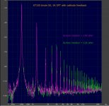
Johan Potgieter said:Also, the argument regarding say 100 - 200 ohms between g2 and anode - the g2 voltage drop for a 6L6 would only be an average of 1V! No way can I see that as making a difference. Make it larger, and the argument in my 1st sentence starts to apply.
Hi Johan. In my single bench test examining the effect of large resistors alone to lower screen voltage the result wasn't very good. The exact operating conditions are forgotten but the only difference in the two distortion spectra below are screen resistor values.
Attachments
We split the thread and took the ultralinear discussion elsewhere:
http://www.diyaudio.com/forums/showthread.php?s=&threadid=97384
http://www.diyaudio.com/forums/showthread.php?s=&threadid=97384
Hi Jkeny,
In the new UL thread you said the ball was taken to be played with over there. I was also guilty (I love your statement!).
But in reality there were 2 balls in the field, and I for one did not realise it until later. The graphs of extended triode operation even appeared the same as for UL. It would seem that concepts of "triode characteristics" were mixed up with "triode operation" - not the same thing.
To stay with your original question, my summing up would be that it would by now be clear that operating the screen at a d.c. voltage lower than the anode but coupled to the anode ac-wise has advantages. I certainly did not see it before, neither thought about it. The advantages are working with a G2 voltage lower than that of the anode, keeping dissipation in order especially for tubes with higher Vmax for the anode than for the screen, and still maintaining conventional triode performance. The penalty cost-wise seems to be small.
The disadvantage that I can see is to take Vg2 too low on downward signal swings, in which case severe 2nd harmonic distortion would set in. In this manner it could happen that the lower Vlimit for the anode would have to be raised sufficiently high (in order to maintain a workable lowest Vg2), that much of the gained anode voltage swing is cancelled. In that sense, the Ia-Va graphs showing a lower available anode swing did not quite make sense to me. Then also the upper Va peak would be reduced because of the lower Vg2 at that point than for a triode. With all that, some claims would seem to me questionable - but I have done no tests, and would certainly like to investigate.
The allied suggestion of operating the screen at a fixed higher than quiescent anode voltage would appear to be a no-no in the long run.
I hope this summary is correct. To repeat, to me personally there appears to be little to be gained by this operation over UL; others have disagreed. We are still thrashing out UL on the other thread. (One must also keep in mind that a "worthwhile" gain in output needs to be some 3dB, which means doubling the available power. It is generally accepted that less than that is not worth-while. Is the above going to give at least that advantage?)
Regards.
Johan,
Thanks for getting back to me on this thread - my comment on the ball being taken by the big boys was in jest - I'm delighted that this discussion spawned what seems to be a fruitfull line of research.
My thread's intention was to get feedback from those who had already tried triode strapping & some feedback on the settings which might apply to my setup as I wanted to try this.
I don't have a UL connection on the OPT & was not intending to purchase new OPTs so if this is as good as UL operation I would be delighted.
I'm keeping an eye on the UL thread & hope that some solid conclusions emerge which might also be applicable in my setup.
Regards
john
Hi Guys,
I would like to try "Triode Trick" in my EL34 PSE amp, unfortunately I have problem to get voltage reference diodes 1N821 in Poland.
I'm wondering what type of diferent diodes than 1N821 I could use "Triode Trick" without spoiling efect of orginal design.
Regards,
Artur
I would like to try "Triode Trick" in my EL34 PSE amp, unfortunately I have problem to get voltage reference diodes 1N821 in Poland.
I'm wondering what type of diferent diodes than 1N821 I could use "Triode Trick" without spoiling efect of orginal design.
Regards,
Artur
- Status
- This old topic is closed. If you want to reopen this topic, contact a moderator using the "Report Post" button.
- Home
- Amplifiers
- Tubes / Valves
- Triode Trick