I'm nearly done with my design and am planning on fusing each output transistor individually along with at each rail. This way, if my output is capable of nearly 5amps max from the supply, each output transistor can be fused at a fraction of the total. When one fails, it will draw the total current through it's fuse, blowing the fuse at it's lower than total rating. Example, 5 amp rail, 4 output devices, each device fused around 2 amps. Easier to blow a 2 amp fuse.
@Synomumous
Your idea is built on the assumption that only one, or two OPS devices would fail, why would that happen in a properly designed amplifier?
With 2A fuses on each device it would mean only individual fuses blows if 1 or 2 devices fail, but when 3 devices fails you have 6A that means the rails fuse of 5A would have to blow, what's the logic?
I'm going to try this one. If sits passively inside a speaker as last resort.
http://www.diyaudio.com/forums/solid-state/313651-speaker-protection-3.html#post5219563
My triacs just arrived today. They are not expensive.
I suppose one could even put a fuse at the speaker so that the crowbar sets it off.
http://www.diyaudio.com/forums/solid-state/313651-speaker-protection-3.html#post5219563
My triacs just arrived today. They are not expensive.
I suppose one could even put a fuse at the speaker so that the crowbar sets it off.
The idea is that in most circumstances, one device failure at a time. Rather than fusing for peak power supply output, I can fuse each device at twice it's power draw, getting better performance from the fuses themselves and faster break. The stresses will be lesser with more fuses sharing the load. The power supply fuse, or rail fuse is inconsequential and more for if one whole rail goes down, it will blow the other side at the supply current rating.
Member
Joined 2009
Paid Member
On my TGM7 there was no output speaker protection incorporated. What I did there was to put a resistor between the power transformer centre tap and the 0V line (speaker return). At audio frequencies the signal return is through the rail capacitors. If you get dc on the speaker it has to return to the centre tap of the power transformer and with the resistor in place you limit the current. You could make it a resettable fuse instead perhaps. Of course, you must have a separate power transformer for each channel. A crow-bar could also be used and the resistor/fuse in the centre tap would respond accordingly. I've never used a crowbar type of protection, seems old fashioned now that we have good SS relays available. Back in the day a mechanical relay suitable for high power dc circuit breaking was a rare beast no doubt and the crowbar a low cost way to protect expensive pa speaker towers from a rogue amp but for hi-if in the modern age I don't see why you would want such a suicidal circuit unless you had really expensive hard-to-replace speaker drivers.
I don't like to put fuses in the audio path as mentioned above. My TGM7 is the only exception, but in that case the fuses are inside the gnfb loop so distortion is reduced by the feedback factor. Still, I don't put fuses in the audio path in my other amplifiers.
I don't like to put fuses in the audio path as mentioned above. My TGM7 is the only exception, but in that case the fuses are inside the gnfb loop so distortion is reduced by the feedback factor. Still, I don't put fuses in the audio path in my other amplifiers.
Last edited:
I've never used a crowbar type of protection, seems old fashioned now that we have good SS relays available.
Do you put a SSR in the audio path or do you switch the rails?
Member
Joined 2009
Paid Member
I put the SSR in the audio path. Completely transparent.
Have you a schematic?
Member
Joined 2009
Paid Member
Try searching, there are many.
e.g. http://hifisonix.com/wordpress/wp-content/uploads/2012/08/Speaker-Relay-V1.03.pdf
e.g. http://hifisonix.com/wordpress/wp-content/uploads/2012/08/Speaker-Relay-V1.03.pdf
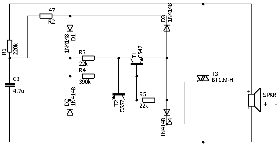
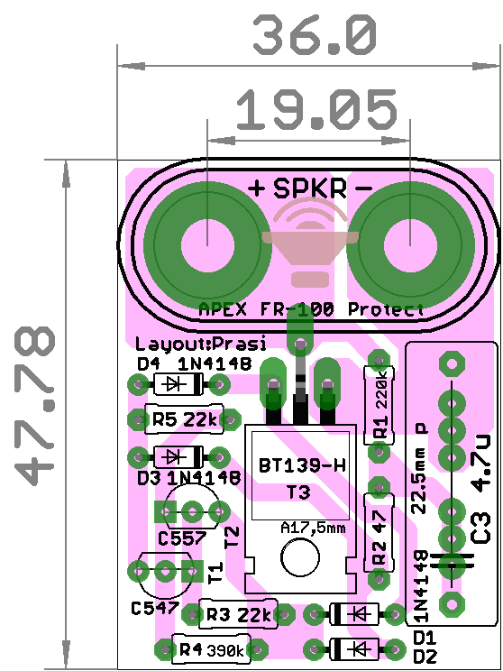
Yorkville uses this TRIAC crowbar circuit, across their product line up to 2,000W.
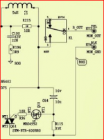
The SSR circuit looks good but the SPICE model does not include a real woofer's voice coil and crossover network inductance, several mH not 20uH lol. So I think the avalanche might kill the MOSFETs.
The SSR circuit looks good but the SPICE model does not include a real woofer's voice coil and crossover network inductance, several mH not 20uH lol. So I think the avalanche might kill the MOSFETs.
Attachments
@synonymous
Thanks for explaining, do you use any other types of safety/supervision circuitry around the OPS?
It's for a LMOSFET design, so I'm set for just zener on gate. Most likely just leave it alone for the device built in protection. Contemplated a multislope for shorts etc.. but I'm not using source resistors so.. I do have clip detection that I've Incorporated in the board that sends the signal to the raspberry pi which will be feeding the amp. With some algorithm, it can be set to do whatever I would like. My default action will be to decrease volume at some increment until the clipping is gone, or hold increases if it's mild. I'm stacking the boards so that there's little to be wired and after the amp section is done, I can possibly incorporate DC sensing and more, killing power etc.. I am leaning towards just individual fuses ATM and perhaps no crowbar. This amp will end up powering a set of solstice kit speakers with woofers that handle 1000w short term, so a 2-3 amp fuse aught to blow before a woofer. If I decide to use a crowbar, it can go in the speaker later. I'll probably devise something for the pi by then in its place. In software there's more options. All the power cycling etc. This thing will have a master power switch on the rear of the chassis and maybe an LED on the front with a USB port. The amp will be on only when it's needed automatically.
@synonymous
Ok I see, I would have expected some type of supervision and an indicator of when any of the individual fuses have blown, sorry if it seemed like I was attacking the idea using multiple sub-fuses out of the blue but I am here still trying to get my head wrapped around seeing any eventual benefits of using individual fuses for each OPS device.
The one potential problem I am still wondering and fearing over what happens when one of the sub fuses blows due to say pushing the amp too much and without any sub fuse supervision circuitry is, the amplifier would continue play music as if nothing had happened due to the blown sub fuse will take out the faulty output device from the amplifier circuit, and here's where I suspect it might get dangerous if things aren't properly dimensioned.
Clipping indicator is now useless as it's (usually) only voltage out, not power or current, but when the power/current share steps down from 4 to 3 devices makes me think it would hereon potentially become an avalanche effect where each consecutive device would blow out easier and quicker until all 4 are blown (that is when only the sub fuses blows), and only then the music get's horribly distorted and the listener would notice something's gone wrong.
The use of sub fuses could work, but me thinks it would require some extra circuitry that cuts the whole amp out from say an excessively too large input audio signal and/or some other faults causing the amp putting out too much power, but of course, if all fuses are deliberately well under-dimensioned it could render the amp "fool-proof" anyway.
Last edited:
I am here still trying to get my head wrapped around seeing any eventual benefits of using individual fuses for each OPS device.
The primary purpose is so that I can measure current flow of each device in normal operating conditions. I am curious as to actual since ive never not used current sharing resistors. I can plug and unplug each and play around easier than soldering and unsoldering. I have considered setting up a circuit that can tell when one is not working and to again, in software, do whatever I want. This isnt really the priority though and will probably SSR the output via Paul Bysouth idea in post TGM 1i - an integrated hybrid amp inspired by Hugh Dean and as well have that sensed by the RPI. Have it email me if theres a problem lol. It will probably be some time before all that stuff is hashed out, so the individual fuses will offer that temporary security as well. Its this little detail of what final parts can go on the amp board before I get them made. Id like to have the amps nearest completion so that I only have to mess with the accessories attached to it, which can have many versions. In the end, i can solder wire each device directly to the power rail and simply have the two rail fuses. Fuses more for test and temporary security. Prototype
Attachments
Back in the days when the linear power supplies were king. you needed a crowbar to save the load if the pass device on the supply shorted. Center-fired SCRs (symmetric gate feed) were preferred over edge-fired to prevent SOA failures due to hot spots from uneven SCR turn-on. Motorola had a line of SCRs for crowbar duty. I don't know that triacs would do the job properly.
Member
Joined 2009
Paid Member
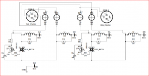
This is what I am probably going with..
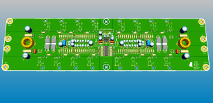
Just the FETs on the amp board, control traced to a master pin header to the accy board. Forgive the silly 3d leads missing the pads.


As a note, Paul Bysouth claims that under test, when lifting a rail fuse, there's no pop associated. The signal just ends. Sounds like a solution to me.
Just the FETs on the amp board, control traced to a master pin header to the accy board. Forgive the silly 3d leads missing the pads.
As a note, Paul Bysouth claims that under test, when lifting a rail fuse, there's no pop associated. The signal just ends. Sounds like a solution to me.
My unknowledgeable fear is that since I am DC coupled DAC to amp, that I do not know the limits of signal reproduction and could possibly trigger a crowbar quite easily. Since I am in some uncharted territory for myself and doing my best to not ask too many questions, I figured this would also be a better way to allow adjustments and have some success without bombing it.
- Status
- This old topic is closed. If you want to reopen this topic, contact a moderator using the "Report Post" button.
- Home
- Amplifiers
- Solid State
- triac's used as crowbar??