Boiss and all,
If you look at the 813 spec sheet, you can run up to 2500v on the plate, but the screen grid is limited to 1100v max and typically used at less. Most amps I have seen run about 900v on the plate so that UL taps are O.K. without dropping networks.
I use a 40khz switch mode power supply of my own design for the filaments. It is both current and voltage regulated. I can go up to 200khz if I wanted to, but the 40khz is fine, with no bad effect whatsoever on the audio output. There is no need to balance out line power hum when this type of supply is used. Also this supply is probably less than one pound and is very small, fitting easily under the chassis. The next best is a transformer/rectifier followed by a linear regulator using 2N3055 transistors to provide D.C. current. This supply needs heat sinks and is much heavier and larger. Plus, there is always some residual hum, no problem if it is down 60db or more.
813's are plentiful and inexpensive. Roger Gould has a pile of them. If anyone is interested, I will post his phone number.
I am a little biased, but my 813 pp amp is the best amp I have ever listened to. I still have to run tests to quantify it, but I have absolutely no hum and no distortion that I can hear at low or high volume. I have friends with ultra expensive commercial tube amps that do not compare with mine.
sparky813 said:Boiss and all,
I am a little biased, but my 813 pp amp is the best amp I have ever listened to. I still have to run tests to quantify it, but I have absolutely no hum and no distortion that I can hear at low or high volume. I have friends with ultra expensive commercial tube amps that do not compare with mine.
A good switcher is indeed an excellent solution: I recall testing the valve illustrated in my avatar (TY4/400) with a switcher. This valve requires 5V at 14A to light it up and a redundant computer unit was perfect. There was very little HF noise displayed on the 'scope when I checked.
And yes, 813 is a super valve. As a triode, with ra of 1.8k and good linearity it is the perfect candidate for those who like big good-looking valves yet who are not millionaires!
7N7
sparky813 said:Boise, I am using a 6SN7 preamp and a 6SN7 phase splitter with cap coupling. This driver works very well in my set up but it is not optimum since the 6SN7's don't quite have the peak voltage rating that is required for full power. My 813's use cathode bias. You know that the 813's are very easy to drive compared to triodes so that exotic driver stage is not needed as much. Good luck. I really like listening to my amp. The only cutting edge technology I am using is to use switch mode power supplies for the filament, screen and plate supplies. Do you have a torroid winder or are you going to wind several thousand wire turns by hand? I have some large cut cores that I considered using and they would be simpler than a torroid to wind. Sparky
Sparky,
OK so you are running P-P and not UL. What are you running for output iron? Plate load Z, Plate B+, screen B+? Class-A, AB1? Power output? Sorry ior all the Q`s, just curious, as I`m sure others are too.
6SN7 & 813
6SN7GTA & GTB are rated at 450V; there should easily be enough voltage swing available.
However the 6SN7 does not have the muscle to drive an 813 in my view - although of course there is probably no finer voltage amplifier!
If you don't like cathode followers then you need a driver that passes a bit of current and has low ra: 12B4A perhaps
7N7
Bob, this is what I have so far for my PP amp, which is an update of an earlier post. This is a work in progress and I intend to try some of the circuits recommended and discussed on this site:
813 output tubes in push pull
ultralinear taps at 40% (no dropping resistors as long as plate voltage under 900v)
custom output transformer of my own design, 3" stack EI-1 3/4, interleaved windings 4section primary, 5 section secondary, .010 Nomex between sections. .005 Nomex between layers. Solenoid wound using an engine lathe with wire tensioning control. Calculated frequency bounds at 20hz and 100khz.
6SN7 phase inverter and driver tubes
Goal: 100 watts rms class A, 200w class AB (scope shows 100w with no crossover distortion - to the naked eye, so far)
So far, I am running 600v on the plate, (final design will be 900v to 1200v. ) I use a SMPS for the filaments and it works very well in addition to being light weight. I am designing a SMPS for the plate supply also, so that the finished mono block will be movable without a fork lift. SMPS Plate supply is 100watts continuous and 200w peak and has been tested at 900v but not hooked up yet.
I use no cathode bypass caps. I have tried a little negative feedback, but no improvement over already good sound.
Sparky,
Sounds like you have been trying a number of configurations there. Good stuff. Winding your own output iron is a class act. My desire would have to be very great for me to tackle that sort of thing. When it comes to transformers with lots of turns I generally put my time and effort into getting the best from what is already wound.
If you only need 200 watts max does it make any sense to boost the PSU voltages to near the max the tube is rated for? You are building what sounds like a big block Chevy engine to spin a pencil sharpener. Believe me, a small block Chevy will do the job just fine.
Do you like the U/L arrangement better sound wise than the regulated screen grid arangement? Sure it will take more G1 drive but besides that issue.
Bob, I could not hear any difference with UL versus DC screen supply. I will post more details on the OPT. I have 4,8 and 16 ohm output and I think it is designed for 10k load line, but I have to go to the shop to dig up the paperwork. The main problem is that there are 23 or so individual windings that must be insulated from each other. and then connected in series or parallel for the interleaved construction. Then, since the OPT is a high voltage application, it must be vacuum pressure impregnated with varnish and dielectric tested to 2X operating voltage plus 1000v, or, in my case I will test to 4kvac, 60hz, 1 minute.
The only exotic equipment, besides a lathe and turns counter is the wire tensioner which is a must for angel hair size wire. A spring loaded pair of felt pads, and a pulley that rides with the lathe cross slide would work O.K. I had no problems except that it took a long time.
The only exotic equipment, besides a lathe and turns counter is the wire tensioner which is a must for angel hair size wire. A spring loaded pair of felt pads, and a pulley that rides with the lathe cross slide would work O.K. I had no problems except that it took a long time.
I used to wind a lot of tesla coil secondaries on a motorized arrangement that spun the coil form, stopped as needed by letting off the foot switch and by laying on the wire by a gloved hand. I found that I could NOT apply #36 wire no way, no how. The friction drag of the wire going over my finger would snap it. #29 AWG was nice to work with on the small 4 inch diameter by 1 to 4 foot long coils.
The bigger ones on 10-12 inch PVC pipe formers were wound with #18 polythermalese HAMT or #18 stranded. One was wound on a fiberglass pipe former at Hammond in Guelph from solid #10 AWG polythermalese HAMT on a big coil winding lathe with tensioner. I would have NEVER done this by hand feeding at that tension. One biggie got #6 stranded laid on by one hand as I rolled the large coil former on a shaft supported by two sawhorses. That didn`t work so well so off came all the #6 and got rewound with twice as many turns of #12 nylon covered stranded. My hands hurt just thinking about that job.
The bigger ones on 10-12 inch PVC pipe formers were wound with #18 polythermalese HAMT or #18 stranded. One was wound on a fiberglass pipe former at Hammond in Guelph from solid #10 AWG polythermalese HAMT on a big coil winding lathe with tensioner. I would have NEVER done this by hand feeding at that tension. One biggie got #6 stranded laid on by one hand as I rolled the large coil former on a shaft supported by two sawhorses. That didn`t work so well so off came all the #6 and got rewound with twice as many turns of #12 nylon covered stranded. My hands hurt just thinking about that job.
Bob,
A little OT, but since you mentioned Tesla coils, I have a friend who is an engineer at Tesla motors, and I am hoping one day soon to have a chance to test drive that electric car. I am into more than just the Audio hobby.
In Seattle, near where I live, some fellows in a club called "Weird Science" set up a very large Tesla coil in the basement of a home. The discharge ball at the top of the coil was near the ceiling. After experimenting with it for a while, someone smelled smoke. They had to tear into the ceiling. Induction from the Tesla coil had set the aluminum foil backed insulation on fire.
Nick,
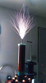
Power tubes with four `odes in them are crappy in the application of a self regenerative power oscillator driving a tesla coil. You want three `odes. a 3PR1000 would be great. I never heard of one though. 833A`s are fantastic and one is a great match to a microwave oven power xfmer. Look what I did with one. 22 inch discharge! 833A`s parallel well and there are bigger triodes to be had.
Power tubes with four `odes in them are crappy in the application of a self regenerative power oscillator driving a tesla coil. You want three `odes. a 3PR1000 would be great. I never heard of one though. 833A`s are fantastic and one is a great match to a microwave oven power xfmer. Look what I did with one. 22 inch discharge! 833A`s parallel well and there are bigger triodes to be had.
Attachments
813 pp
Ok, did some testing on my toroid. I wanted to get some idea of the inductance but have only a scope, so I made a little hartley osc with a BC177. With some caps across the transformer I got a resonant freq of 28Hz giving me an inductance of 45H. Removing the caps the resonant frequency rose to about 60KHz giving a total capacitance in circuit of about 20pF, this includes the winding capacitance, the series 10pF in the base circuit, the collector capacitance and the scope probe capacitance.
The winding resistance anode to anode is 40 Ohms.
I'm not an expert on transformers so what are your thoughts?
Boiss
sparky813 said:Bob,
A little OT, but since you mentioned Tesla coils, I have a friend who is an engineer at Tesla motors, and I am hoping one day soon to have a chance to test drive that electric car. I am into more than just the Audio hobby.
In Seattle, near where I live, some fellows in a club called "Weird Science" set up a very large Tesla coil in the basement of a home. The discharge ball at the top of the coil was near the ceiling. After experimenting with it for a while, someone smelled smoke. They had to tear into the ceiling. Induction from the Tesla coil had set the aluminum foil backed insulation on fire.
Been there, done that. It was my first fairly large coil and I got carried away with the awesome phenomenon I was experiencing for the first time. Fire got hold in the ceiling while I was sleeping. I was incredibly lucky that I woke up and smelled smoke. I lived. That is not a mistake you make twice. After that the coil went outdoors to test. Threw an 18 footer first light! Yeah, it was a bit too big for my living room lab.

I am in the process of designing an electric motorcycle including a DIY PWM controller. It is the cheapest EV I can make that is a real vehicle and can serve as a learning experience. I might think of a car later on. Diesel electric hybrid suits my fancy. Too many proyects on the go though. Not enough life left to finish all I want to do.
There are a lot of high power triodes used in industry as induction heaters, etc. They are almost always self excited oscillators. If it were better to run a tetrode driven by a exciter then that would be common. It ain`t. The tesla coil represents a very abusive load. I`ll put money on your screen grid melting first day.
Anyhow, it`s your tube.
Anyhow, it`s your tube.
- Status
- This old topic is closed. If you want to reopen this topic, contact a moderator using the "Report Post" button.
- Home
- Amplifiers
- Tubes / Valves
- transmitter tube amp