mclsound said:thank you Mark,
it will be put behind the woofer only for tuning,not throughout ...
have you tried this product??
john
Yes, have tried . . . but only for sleeping on!
'Not tested for speaker damping. Likely reflective at some frequencies due to closed-cell construction.
-- Mark
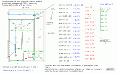
hi B,thanks for getting back,i have drew up some more accurate #'s.......the exit line slopes...here we go
a-1---9.25 s-11---8.50 s-0---1
2------4.25 12---11.875 1---24.50
3------8 13---4.25 2---9
4------11.75 14---4.125 3---20.625
5------8 15---3.875 4---7.625
6------10.25 16---3.625 5---28.75
7------7.5 17---13.625 6---21.625
8------6.75 18---3.50
9------9.25 19---3.25
10-----6.75 20---3.25
11----9.75 21---3.50
12----6.75 22---25.75
13----6.75 23---3
14----8.75 24---3.25
15----6 25---18.375
16----5
i left .5"around the exit opening for some foam cover(??),some where to glue to. these should be closer,thanks again for your help,i learn more every day
john
hi b ,thank you for this help. but i am not sure what all that means???????????
is there room for improvements,the graphs need a little explanation for me if you can please,
my prototype does not go as low as the PMC IB1,i do know it all takes time ...one step at a time i say. look forward to your response as always.....i may have been off by a tiny bit here and there but they are very very close.
i chose a bigger box design because i know the volt 3143 is not a modified pmc version,may be i should have stuck with the pmc dimensions????
do you think i can get this design i created to dig down low(20-25hz at 100 db) and still be accurate.????
thanks john
hi B, my goal is to get a solid 20-25hz at 95-100db out of a cabinet and yet have it still accurate.......if i can use this cabinate i will or if i have to start over i will and make it 34"hx22"dx15"w ?
i would make it out of 1"mdf with .25 red oak outside and inside for a 1.5" sandwich design...i would not know the inside line dimensions though??
but if i can use what i have then great,although it is a bit large!!
thanks John
i would make it out of 1"mdf with .25 red oak outside and inside for a 1.5" sandwich design...i would not know the inside line dimensions though??
but if i can use what i have then great,although it is a bit large!!
thanks John
…hi B, my goal is to get a solid 20-25hz at 95-100db out of a cabinet and yet have it still accurate…
Yes you can but with an IB sloping Fr curve I find more desirable than one with a flat FR.
Hi John,
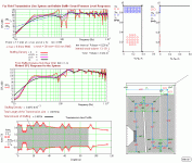
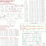
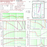
In my latest posted simulations besides the equivalent resulting very low Qt value, I especially noticed the TL length of 109.34” that I find somewhat too long.
This length is equivalent to a straight quarter-wave pipe at a resonance of 31 Hz, empty with no stuffing.
The driver fs of 34 Hz can be considered to be near quarter wave matched for this empty straight pipe.
When this pipe is tapered, the tuning of the empty cabinet results in a quarter wave frequency that is lower i.e. 25 Hz and when filled with stuffing material (typical density around 0.5 lb/sq ft), tunes the cabinet even further lower, in this case to the very low frequency of 22.4 Hz.
Using this woofer in a cabinet volume of 237 L (= 3.1 x Vas) results into an equivalent Qt = 0.4(driver equivalent f-3 dB= 82 Hz, fc at 39 Hz) and the tuning at 22.4 Hz is very low for a TL using a driver with fs= 34 Hz.
By the way, the driver maximum-ported volume is recommended to be 110 L/ tuning at about 25 Hz (Qt = 0.455/ driver f-3dB = 78 Hz and fc = 44 Hz).
The result of this very low tuning can be seen at ‘ Woofer and Terminus Far Field Sound Pressure Level Responses’ in the previous picture: 3-Volt RV 3143-TL-cont1_rev1 where the contribution from the terminus is low due to the restricted and narrow tapering, not to forget the many bends that acts as lossy low pass filters. You can’t ask for more with this type of multi bend folded TL.
In the corresponding phase plot, above the SPL plot, you may notice how the terminus is summed to the driver SPL*.
When the phase difference is < = 90 degrees the terminus sums to the driver constructively.
For this case the in band is within about 75 Hz down to 23 Hz at a pivot frequency of about 47 Hz where the phase difference is 0 (correlated) and sum linearly i.e. 94dB(driver) + 91dB(terminus) = about 97 dB.
At the quadrature points the sum is less and can be seen to be: at 23 Hz where the terminus is at 85 dB and the driver at 90 dB gives the sum = about 91.7 dB.
The upper limit is at 75 Hz where the terminus is 92.7dB and the driver at 97.7dB which sums to about 98.5 dB. All of this gives a FR slope of about 6 dB/octave.
*//Lp =((10^(94/20) +10^(91/20) = 10^(4.7)+ 10^(4.505) =10^(4.914) which is in dB SPL =20x log (10^(4.914)) = 98.29 dB SPL as seen in the summed SPL plot.
To sum the driver and terminus at the quadrature points (90 degree phase difference) the following equation can be used:
Lp (dB SPL) = 20 x log (sqrt (10^(SPL (a)/20)+ 10^(SPL (b)/20) +2 x (10^(SPL (a)/20) x 10^(SPL (b)/20)) x (cos (the phase difference between a and b)); cos 90 degrees = 1 reduces this equation to
Lp (dB SPL) = 20 x log (sqrt (10^(SPL (a)/20)+ 10^(SPL (b)/20) +2 x (10^(SPL (a)/20) x 10^(SPL (b)/20))//
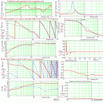
Above 75 Hz within about an octave the sum of terminus and driver SPL: s is counteracting each other and results in the dip centred at about 93 Hz.
In the practice this Sub will be placed at the floor, near a wall and when adding the baffle step, diffraction and wall-floor mirroring effects, a flat response (shelf like) up to about 90 Hz can be achieved with an f-3dB of 25 Hz at an in band level of about 98.5 dB maximum, x-max protected at 1 Hz.
If flat100 dB SPL is the goal at 25 Hz, then the input power must be restricted by using of an active HP filter protecting the driver from over excursion into the driver non linear x-max region together with a LP filter (sub amp) at about 80 Hz to suppress the ripple at higher frequencies or redesign to a shorter TL that have far less ripple and smother FR.
About 106 dB is achievable with an input power of 45 W equipped with an active12 dB/octave HP filter at 20 Hz.
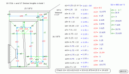
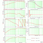
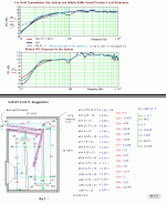
Look at the submitted pictures where the TL taper is increased and the length is shortened (fig 1), in my opinion, with performance that is more accurate that can be further improved if the layout in (fig 2) is used.
I suggest: Back to the drawing board and rework the internals of your cabinets, to a shorter folded layout where the terminus is 13” x (2.5”-2 7/8”).
b
1(4)
Attachments
hi B,i was wonderinging if it is achievable to clone the mb2 style with the 3143......the mb2 is 124db/1m and line length of 10 feet in a 3 chamber cabinet reaching 20hz.
now with these calculations(your new ones)our line is going to be 79"(6'7") in a 2 chamber cabinet reaching 100db/1w/1m at 25hz(approx)without the atc75/150(non s) and the ss9700 added in the spl reading....i am currently using a bryston 10b lr(24db) in 2-way and crossed at 380hz and just added a 24db passive for mid/hi at 3800hz ...a bryston 14bsst on low and a bryston 4bsst on m/h....unfortunately i glued and screwed the cabinet so i may have to start all over and if so i will make it a little smaller or do you have any other suggestions...once again B i thank you for your help.
my goal is a VERY loud accuate box that will exceed past my PMC IB1 in performance. with your help B we will do so.
thanks John
….i was wonderinging if it is achievable to clone the mb2 style with the 3143......the mb2 is 124db/1m and line length of 10 feet in a 3 chamber cabinet reaching 20hz….
Hi John,
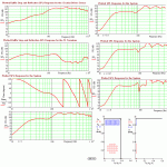
I have already shown that when using the RV3143 driver in a folded straight-line TL-length beyond 8.2’ (a quarter wavelength at 34 Hz) implies exceeding the limit where a smooth FR can be achieved, thus a 10’ - 3 chamber compact multi-folded cabinet is not reaching 20 Hz without a lot of SPL loss and bad FR behaviour.You can of clone the MB2 style and size but I recommend restricting the line length in favour for larger CSA ratios.
Its not difficult to clone a speaker if you are using a driver you know meets data parameter-wise the original, but cloning a supposed performance claim like 124 dB/octave including the extension down to 20 Hz stated without supported detailed data of the MB2-driver(cabinet internals too) to back this up, is to entering wishful thinking into the equation.
If PMC is using the Volt RV3143 driver I think the 124 dB SPL claim only is a gross marketing hyperbole in order to impress.
…now with these calculations(your new ones)our line is going to be 79"(6'7") in a 2 chamber cabinet reaching 100db/1w/1m at 25hz(approx)without the atc75/150(non s) and the ss9700 added in the spl reading....i am currently using a bryston 10b lr(24db) in 2-way and crossed at 380hz…
I think my TL calculation match the ATC well 91 dB/1m/1W at a level of 92-93 dB SPL/1m/1W but at 25 Hz the level is at the modest 82 dB SPL/1m/1W and not 100 dB SPL.
100 dB SPL is referred to the midband level when the input power is 7.5W i.e. when x-max occurs at 1 Hz, 25 Hz corresponds to 91 dB SPL at this power level.
I’ve calculated the maximum SPL (at 380 Hz 2 PI Steer Radians) for the ATC midrange to be 98.7 dB (x-max limited), 104.7 dB SPL if 537 Hz, 110.8 dB SPL if 760 Hz and at 1627 Hz the maximum level is 124 dB SPL but this later SPL value is not realistic due to the power handling is restricted to 150 W and max 112.8 dB SPL where the driver reaches its thermal limit.
In other words the claim of 124 dB SPL for the Volt driver is also quite useless input parameter as the ATC driver is restricted at max to about 113 dB.
The Scan Speak driver is thermal limited at about 113 dB SPL (2PI SR) or excursion limited at 3300Hz, excursion limited at 1550 Hz for 100 dB SPL and at 2kHz excursion limited for 104.5 dB SPL.
To sum up you have to relax your SPL requirements or redesign using more capable drivers: Lowest XO points adds up to be at about 380 Hz and 1550 Hz at a maximum level of 98 dB SPL or 105 dB SPL if XO: ed at 540 and 3.3 kHz.
Note: Usable pass band levels is about 3-6dB higher due to the SPL: s is for an odd filter 3 dB or an even filter 6 dB down at the cross over frequencies.
…i will sart over with the MB2 dimensions .......if you could help with internals i would be in your debt…
I see no debt at all
") , though it would be nice if you (later) post your detailed design drawings and if possible, include pictures of your speaker’s too.
, though it would be nice if you (later) post your detailed design drawings and if possible, include pictures of your speaker’s too.Hi John,
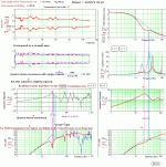
113 L is a perfect volume to use with the RV3143 and I would try a MLTL design placing the T driver at ear height in a narrow (width) design.
If folding a TL I always try to avoid 180-degree bends if possible or restrict to include at most one.
The easiest method to layout a folded Tl is to layout (plot) the TL un-folded on a piece of paper, then by using a pair of scissors cut out at all the CSA: s that is connected with a straight section line, i.e. to form a puzzle of (sometimes) many pieces and then put together in the way that suits a compact cabinet.
b
- Status
- This old topic is closed. If you want to reopen this topic, contact a moderator using the "Report Post" button.
- Home
- Loudspeakers
- Multi-Way
- Transmission Line Question