The idea is great, it seems now a little bit difficult to design a system, but the ability of add tubes to eq the response is just perfect to me.
When you try to minimize the GeometryDisplay from the taskbar it gives an error.
Yes, I agree. I intend to make it so you can enter the TL in a similar way as before and the 'new' way as a kind of advanced mode. I think I know what the bug with geometry window is. I'll try and fix that tomorrow if I get chance.
@wheeee!
Seriously, this is cool. Just answered a crazy question I had last night. Yes, if you mount your TL on a box, you can use that box to control the output. (I think.... the program says so.... we'll see what happens when I build it.) (Not so much a box as a hollow fence post.)
Anyway, I think this might open up a lot of possibilities for those more creative souls among us.
In the enclosure window, the only way to know which element's data is displayed is the highlighting on the tree. This gets lost when you do an update.
The 'Acoustic Radiation Impedance' is a flat line. That doesn't seem right.
Last edited:
Yes, I agree. I intend to make it so you can enter the TL in a similar way as before and the 'new' way as a kind of advanced mode. I think I know what the bug with geometry window is. I'll try and fix that tomorrow if I get chance.
One idea, for example, when you want to add a branch in a specific point of the geometry, you define the first element, then add a second element and then add a branch at the second element, that will be at the beginning of the second element, you need two elements and a branch to define the geometry, if you want more branchs at diferent points you´ll need (number of branchs)+1 elements, but if you define a branch for the distance of the branch from the beginning of the element where it is, you´ll be able to define multiples branchs easily.
English is not my languaje, hope that anyone could understand this

New update (2.9.3) has fixed a couple of the problems found so far.
- Added Element Title information to the Element edit form so you know which element you are editing.
- Fixed bug where program crashes when you minimise the geometry window.
- Upgraded velocity graph so it displays the velocities of each open ended branch.
- Changed acoustic radiation impedance graph to driver radiation impedance.
Akvaro,
I follow what you mean and I thin kit is a good suggestion, although quite hard to implement with the way I have coded the program. I think a 'Split Element' tool would be quite helpful also. So you can create an element the full size of the pipe, split it where you want the branch and then add the branch.
I follow what you mean and I thin kit is a good suggestion, although quite hard to implement with the way I have coded the program. I think a 'Split Element' tool would be quite helpful also. So you can create an element the full size of the pipe, split it where you want the branch and then add the branch.
Looking good.. any chance of some instructions to tell us TL newbies how to use it?
Hopefully at some point!
I'm struggling to find time to do the development, but hopefully I'll be able to put together a help file of some sort at some point..
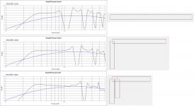
The attached image shows some simple geometries to give an example of what I think is possible by using multiple side branches.
You can see that there is less ripple from the upper harmonics using two side branches over one.
I haven't quite figured out how to determine what size these side branches need to be yet as it doesn't quite react how I thought it would. I'll keep playing though and see what i come up with...
You can see that there is less ripple from the upper harmonics using two side branches over one.
I haven't quite figured out how to determine what size these side branches need to be yet as it doesn't quite react how I thought it would. I'll keep playing though and see what i come up with...
Attachments
Hopefully at some point!
I'm struggling to find time to do the development, but hopefully I'll be able to put together a help file of some sort at some point..
Know what you mean, so many ideas to put into code its hard to do the boring bit... but when your ready...
Just wanted to mention this converter I found:
Convert for Windows - joshmadison.com
I have four different calculators, but this little app is easier to use, with less clicking. It remembers the last session, you can hide unused tabs, transpose the conversion, and run multiple copies (I keep one open for area, and another for length). The only flaw is you can't paste values into it.
schmeet, I do hope you bump the "units conversion" thing up your list of priorities.
More work for you, schmeet! :0
In the Enclosure window, could you link the "update" button to the "edit" button? Hitting "update" presumes you meant to make the edits, and there's no visible sign the edits were made (aside from the re-hilighting of the element affected). But other than reducing the chance of errors, it would enhance workflow when tweaking dimensions.
Instead of:
tweak number, click Edit, click Update, look at graph, sigh, tweak number, click Edit, click Update, look at graph, sigh, tweak number, click Edit, click Update, look at graph, sigh, tweak number, click Edit, click Update, look at graph, sigh....
we could:
tweak number, click Update, look at graph, tweak number, click Update, look at graph, tweak number, click Update, look at graph, tweak number, click Update, look at graph, smile....
Obviously, the less clicking the better.")
In the Enclosure window, could you link the "update" button to the "edit" button? Hitting "update" presumes you meant to make the edits, and there's no visible sign the edits were made (aside from the re-hilighting of the element affected). But other than reducing the chance of errors, it would enhance workflow when tweaking dimensions.
Instead of:
tweak number, click Edit, click Update, look at graph, sigh, tweak number, click Edit, click Update, look at graph, sigh, tweak number, click Edit, click Update, look at graph, sigh, tweak number, click Edit, click Update, look at graph, sigh....
we could:
tweak number, click Update, look at graph, tweak number, click Update, look at graph, tweak number, click Update, look at graph, tweak number, click Update, look at graph, smile....
Obviously, the less clicking the better.
Hi Schmeet,
a question on v 2.9.4.0, maybe I missed it but I can't find where I can offset the driver.
A good website describing filters and the associated math if you find the time to add that feature (would be very nice to have): Active Filters
a question on v 2.9.4.0, maybe I missed it but I can't find where I can offset the driver.
A good website describing filters and the associated math if you find the time to add that feature (would be very nice to have): Active Filters
Hi Mark.
On the new version you have to offset the driver by having a branch at the start of the line. If you think about it an offset driver is just a branch at the driver to two lines, one open and one closed. This is what you have to model.
So, if you want a 2m line that is offset by 0.3 then you would make the first element a branch with one side 0.6m long and closed, the other 1.4m with an open end.
That make sense?
Thinking about this, what's needed is a "taper ratio" input.On the new version you have to offset the driver by having a branch at the start of the line. If you think about it an offset driver is just a branch at the driver to two lines, one open and one closed. This is what you have to model.
That is, you could input either the beginning area or the end area and a taper ratio, and the program would calculate the other value. You'd also want (radio button) check boxes to hold the beginning or end constant as the length was changed.
This would facilitate moving the offset of the speaker in a typical tapered line without restricting the creative freedom of making the two branches different, if you so chose.
Thanks again for your program, schmeet. It's become my main tool, meaning I use it several hours every day.
Mark,
The way the program works now makes entering a "typical modern TL" awkward, but the trade off is the ability to model many other enclosure types and things that don't even have names, yet.
Decide on the total length of a line you want to model, the taper ratio, the beginning area, and the offset ratio. Say, 2 meters total length with a 4 to 1 taper, a 1 square meter beginning area and the driver offset a third of the way down the line.
Start the program with the appropriate driver selected, and then in the first element, enter:
The beginning area multiplied by the taper ratio as the 'end area'.
1 * 1 / 4 = .25
The 'end area' multiplied by the inverse of the offset ratio as the 'start area'.
.25 * 3 = .75
The total length, less the total length multiplied by the offset ratio, as 'length'.
2 - (2 * 1 / 3) = 1.33
Click 'Edit'.
Click 'Add Branch'.
Choosing the branch element, use the 'start area' of the first element as the 'start area' of the branch.
Use your beginning area as the 'end area'.
Set the branch 'length' equal to the total length multiplied by the offset ratio.
Click 'Edit'.
Click 'Update'.
There, I think I got it right. Yell at me if it doesn't work.
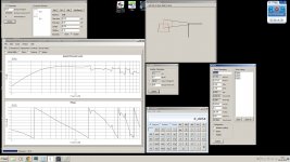
(BTW, if you look at the GeometryDisplay window, you'll see the branch element shown 90 degrees to the first element. This is odd, but normal. The red lines should make a perfect square cross, indicating that their areas are equal.)
The way the program works now makes entering a "typical modern TL" awkward, but the trade off is the ability to model many other enclosure types and things that don't even have names, yet.
Decide on the total length of a line you want to model, the taper ratio, the beginning area, and the offset ratio. Say, 2 meters total length with a 4 to 1 taper, a 1 square meter beginning area and the driver offset a third of the way down the line.
Start the program with the appropriate driver selected, and then in the first element, enter:
The beginning area multiplied by the taper ratio as the 'end area'.
1 * 1 / 4 = .25
The 'end area' multiplied by the inverse of the offset ratio as the 'start area'.
.25 * 3 = .75
The total length, less the total length multiplied by the offset ratio, as 'length'.
2 - (2 * 1 / 3) = 1.33
Click 'Edit'.
Click 'Add Branch'.
Choosing the branch element, use the 'start area' of the first element as the 'start area' of the branch.
Use your beginning area as the 'end area'.
Set the branch 'length' equal to the total length multiplied by the offset ratio.
Click 'Edit'.
Click 'Update'.
There, I think I got it right. Yell at me if it doesn't work.
(BTW, if you look at the GeometryDisplay window, you'll see the branch element shown 90 degrees to the first element. This is odd, but normal. The red lines should make a perfect square cross, indicating that their areas are equal.)
Hi Schmeet & Keriwena
Thanks for the help, it all makes sense to me now. as we say in Dutch "het kwartje is gevallen"!
The sim is a double Dayton Audio RSS256HF-4 each powered by it's own amp (Hypex PSC2.400D at max continues power), squeezed into a 65L enclosure..
Thanks for the help, it all makes sense to me now. as we say in Dutch "het kwartje is gevallen"!
The sim is a double Dayton Audio RSS256HF-4 each powered by it's own amp (Hypex PSC2.400D at max continues power), squeezed into a 65L enclosure..
Attachments
Last edited:
- Home
- Design & Build
- Software Tools
- Transmission Line Modelling Software