With all the counterfeiting of transistors going on, I feel the need to test all the ones I have (as well as future purchases). I'm looking to build a test rig (or rigs) for this purpose. Ideally, I would like to be able to do 4 tests:
1. Basic hfe test
2. Device matching with in-circuit type voltage & current values
3. Variable high voltage/low current stress test for Vce (within SOA)
4. Variable low Voltage/high current stress test for power handling (within SOA)
#1 is pretty straightforward & there are circuits floating around on the internet.
#2 will be someting along the lines of Anatech's circuit.
#3 & #4 are what I'm really looking for help on. I'd love to have a single PS for both, but realize that I may need 2. I have no experience with SWPS's, but I'm open to suggestions if that is the best solution. I really want to have variable voltage so that I can control the tests (and record where the fake ones pop") ). I also want to make sure that if the DUT fails, there is some protection scheme so that nothing else is damaged.
). I also want to make sure that if the DUT fails, there is some protection scheme so that nothing else is damaged.
Specifically, I'm looking for pointers on the best way to approach building 1 or 2 power supplies that are variable from 0-10VDC and deliver up to 10A of current and/or be variable from 50-200VDC and deliver up to 100mA of current. Fusing is the obvious protection scheme, but is current limiting a better option (including handling a shorted transistor)? I'm thinking that using something like 1ohm resistors in the base & emiiter circuits is the best way to monitor what's happening during the tests, but I'm open to other options.
Any input would be greatly appreciated. Thanks!
1. Basic hfe test
2. Device matching with in-circuit type voltage & current values
3. Variable high voltage/low current stress test for Vce (within SOA)
4. Variable low Voltage/high current stress test for power handling (within SOA)
#1 is pretty straightforward & there are circuits floating around on the internet.
#2 will be someting along the lines of Anatech's circuit.
#3 & #4 are what I'm really looking for help on. I'd love to have a single PS for both, but realize that I may need 2. I have no experience with SWPS's, but I'm open to suggestions if that is the best solution. I really want to have variable voltage so that I can control the tests (and record where the fake ones pop
). I also want to make sure that if the DUT fails, there is some protection scheme so that nothing else is damaged.Specifically, I'm looking for pointers on the best way to approach building 1 or 2 power supplies that are variable from 0-10VDC and deliver up to 10A of current and/or be variable from 50-200VDC and deliver up to 100mA of current. Fusing is the obvious protection scheme, but is current limiting a better option (including handling a shorted transistor)? I'm thinking that using something like 1ohm resistors in the base & emiiter circuits is the best way to monitor what's happening during the tests, but I'm open to other options.
Any input would be greatly appreciated. Thanks!
Or find a curve tracer - or build one.
Looking at ebay, buying one is pricey. I will do some searching on building one. Thanks for the tip.
Instead of #3 you should measure reverse currents and break-down voltages, it is more informative.
Hi
How do we measure reverse currents and break-down voltages ?
Thanx
Paul
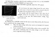
The only crucial component in the LTC905 is a multitapped transformer secondary for the individual sweep voltages. As it is rectified but not filtered to provide a 100Hz (120Hz in the US) sweep frequency, I could measure the actual secondary taps and it would be easy enough to have one wound to suit. The Tx/former has 12-0-12, 12-0, & (0-10,20,30,40,50,60,80,100v) secondaries. The rest of the circuitry is bog standard components.
Output is XY to your cro for testing TR/FET/MOSFETS/SCRs/TRIACs/diodes/zener/tunnel etc.
Breakdown can be determined with this unit.
Output is XY to your cro for testing TR/FET/MOSFETS/SCRs/TRIACs/diodes/zener/tunnel etc.
Breakdown can be determined with this unit.
Attachments
Hi
How do we measure reverse currents and break-down voltages ?
Directly. Open any datasheet for a clue. They specify maximal reverse currents for given voltages. Apply a voltage and measure current.
How to measure breakdown voltage I explained in my previous post: supply a voltage higher than a breakdown one, but limit it's current. How would you measure a breakdown voltage of a Zener diode? The same.
However, a curvetracer is a very convenient tool for such measurements.
if anyone wants a copy of my curver tracer manual and schematic (it's definitely a do-able DIY project) PM me.
My curver tracer is a Leader LTC905 with AB comparison facility
How does the Leader compare to the B&K 501A?
Elektor curve tracer
The Feb. 2009 issue of Elektor offers up a DIY curve tracer to be used with a PC: http://www.elektor.com/magazines/2009/february/transistor-curve-tracer.810360.lynkx
I don't know much about curve tracers, but I remembered seeing the article and it might be of interest.
george
The Feb. 2009 issue of Elektor offers up a DIY curve tracer to be used with a PC: http://www.elektor.com/magazines/2009/february/transistor-curve-tracer.810360.lynkx
I don't know much about curve tracers, but I remembered seeing the article and it might be of interest.
george
Perhaps this could be useful:
http://www.dutchforce.com/~eforum/index.php?showtopic=28929
http://www.dutchforce.com/~eforum/index.php?showtopic=28929
Be aware that you can permanently degrade the noise figure of semiconducters by testing reverse breakdown limits etc. At worst you may significantly impair the device in other ways... long term reliablity etc
Measuring hfe with a view to matching is fine if done carefully.
Other than that, I would only buy from guaranteed sources for any "serious" project.
Measuring hfe with a view to matching is fine if done carefully.
Other than that, I would only buy from guaranteed sources for any "serious" project.
Hi,
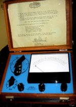
may I warmly recommend this completely harmless, environmentally friendly and esthetically inviting precision instrument for all kinds of real world testing, unassumingly called "The Hubbard Electrometer". Much more accurate than SPICE simulation. Hand-signed & authenticated so it won`t disappoint you.
may I warmly recommend this completely harmless, environmentally friendly and esthetically inviting precision instrument for all kinds of real world testing, unassumingly called "The Hubbard Electrometer". Much more accurate than SPICE simulation. Hand-signed & authenticated so it won`t disappoint you.
Attachments
When I was learning how to use the curver tracer, I used to just wind up the sweep voltage until the transistor 'broke down' not actually dead or anything. I have never hurt one yet or degraded one. I once left a small signal on twice its rated ceb voltage all day (forgot about it) and it was (warm) but fine.
I use it for matching front end differential TRs primarily and checking outputs when they are in multiple pairs. Mosfets are good to test also.
I picked it up at a flea market for $15 with probes (the in circuit probe is a scary thing on its own).
I use it for matching front end differential TRs primarily and checking outputs when they are in multiple pairs. Mosfets are good to test also.
I picked it up at a flea market for $15 with probes (the in circuit probe is a scary thing on its own).
The Feb. 2009 issue of Elektor offers up a DIY curve tracer to be used with a PC: http://www.elektor.com/magazines/2009/february/transistor-curve-tracer.810360.lynkx
I don't know much about curve tracers, but I remembered seeing the article and it might be of interest.
george
I haven't read the article yet (it took very long for them to send the confirmation email to me), but I'm guessing by the looks of it that it is limited in how much voltage is available for testing?
Perhaps this could be useful:
http://www.dutchforce.com/~eforum/index.php?showtopic=28929
It looks like that is specifically desgined to test vacuum tubes.
Be aware that you can permanently degrade the noise figure of semiconducters by testing reverse breakdown limits etc.
Only testing b-e breakdown voltage, and only of BJT transistors, and not permanently: heating up the die you can restore it completely.
b-e breakdown voltage testing is not needed at all, if transistors will be used in most of applications.
Hi,
may I warmly recommend this completely harmless, environmentally friendly and esthetically inviting precision instrument for all kinds of real world testing, unassumingly called "The Hubbard Electrometer". Much more accurate than SPICE simulation. Hand-signed & authenticated so it won`t disappoint you.
Ironically, I know someone who's interested, though I don't know why you would part from such a treasure!
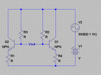
I think this circuit would be good for AB testing of transistors. Any deviation from 0 on the output represents a mismatch.
- keantoken
Attachments
- Status
- This old topic is closed. If you want to reopen this topic, contact a moderator using the "Report Post" button.
- Home
- Amplifiers
- Solid State
- Transistor Testing Rig