First I have measured it and then your calculation is wrong! The roll off is given considering the Req....
You are right, wrong calculation ! ...Touché

BTW, can you please explain that ? I don't understand.
However one can redistribute the capacitance to get it back at lower values by horizontal sectioning.
The capacitance can be redistributed. One case where one does it "automatically" is the PP OT with intermediate flange.
One way to verify this is measuring the resonant frequency with the secondaries shorted in two cases for a single cave SE OT: grounded and floating (with the core and the primary always having reference to ground). You only need a generator in series with the primary and close the loop with a small 10R precision resistor. In parallel to that resistor you put a precision milli-voltmeter. You will get a minimum current at the (first) resonance (parallel type). When you switch from shorted grounded secondaries to shorted floating secondaries the resonant frequency will increase because you are redistributing the voltages and in the latter case it is as if the capacitances were all in series.
If then you do the same with PP OT and balanced generator you won't get that increase! Because of the geometry the distribution is already as if they were all in series.
Took me a lot of time, but I think that now I get it
Surely you have meant "Vertical Sectioning", that is!
For a transformer with grounded short circuited secondaries, (secondaries are almost 0V equipotential) can be proven that effective capacitance referred to +B is
Ce = (nı/N)² Cı
Where
Cı = capacitance between two adjacent P and S windings
nı = number of layers from reference +B to layer midpoint at the interphase
N = total number of layers
We have m interphases, and capacitance "seen" by anode of the valve (generator) is distributed as
Ce(total) = ∑ (nı/N)² Cı ı=1,...,m
In a rough aproximation we can take
C1 = C2 ... = Cm = C
Where C is the average capacitance between two adjacent P and S windings, then
Ce(total) ≈ C ∑ (nı/N)² ı=1,...,m
Suppose now that primaries are left floating, then
Ce = [(2nı-N)/2N]² Cı
Then, capacitances are distributed as
Ce(total) = ∑ [(2nı-N)/2N]² Cı ı=1,...,m
Or
Ce(total) ≈ C ∑ [(2nı-N)/2N]² ı=1,...,m
Clearly, capacitance has decreased, and with an adequate winding pattern could say that "is as if the capacitances were all in series", but in the general case you only can say that capacitance has decreased.
Note that for a winding pattern like 4P-S-4P, we obtain Ce ≈ 0.5 C for short circuited grounded secondary, and Ce ≈ 0.008 C for short circuited floating secondary.
If with "the PP OT with intermediate flange" you meant a PP OPT with vertical sectioning, I'm afraid that your explanation is wrong.
For any respectably constructed PP OPT, regardless of vertical sectioning, if short circuited secondaries are left floating, they still remain at 0 VAC, because each extreme of primaries beside secondaries, is at +U V, and the corresponding symmetric opposite extreme referred to +B (ground) at -U V, push-pull works thereby. AFAIK
So no redistributed voltages, so capacitance remains unchanged, that is!
That "horizontal sectioning" is not precisely referred to the geometry. That "intermediate flange" I think is rather obvious! Popillin, I see your torment and you want to prove something where you can say I am wrong but there is no chance!
This thread remains CLOSED for me and I will not certainly tell you anymore because I don't think you deserve further explanations. As it has been re-opened you can go on forever with you logorrheic writing if you like.....without having made any transformer yet!
Even less other people that few months ago didn't know what a characteristic impedance is and now think that they make the best transformers in the world without knowing how it really works!
Last edited:
diyAudio forum has more than 300000 members, many come here to learn, including me, we are here to help each other, I'm just a TV repairman but I think is my duty to correct as many mistakes as I can with my limited knowledge.
Your continuous mistakes and misunderstandings can be detrimental and don't help us too much, is nothing personal against you, but for the good of this community.
OK, but if you use terms outside of transformers jargon, at least you must clear that you really meant.
My torment is thinking in the people that come here searching for correct information about transformers.
Seems to me that you think so from the beginning, because I made you a lot of questions without any answer.
I'm poor, and living in the third world make me extremely difficult to obtain good transformers, so I decided make them by myself a long time ago, however I realized that information about transformers is scarce and nothing reliable, so I took the trouble to deduce all the equations (except that for Ls) starting from Maxwell Equations.
All that information was shared here on the forum, and it is subject to critique and update, and I think it is useful, not only for me.
What about yours? You haven't posted any equation, nor those I asked you, neither that you said you use.
Took me an enormous effort to make my own transformers and I have no need to prove anything to anybody.
The OP did a wonderful transformer, and you still criticize him.
"Extraordinary claims require extraordinary evidence." - Carl Sagan.
Unlike the OP you have made extraordinary claims without any proof.
On another thread you claim having a PhD in Physics, please be at its height and think a little more before posting.
Your continuous mistakes and misunderstandings can be detrimental and don't help us too much, is nothing personal against you, but for the good of this community.
That "horizontal sectioning" is not precisely referred to the geometry. That "intermediate flange" I think is rather obvious!
OK, but if you use terms outside of transformers jargon, at least you must clear that you really meant.
Popillin, I see your torment and you want to prove something where you can say I am wrong but there is no chance!
My torment is thinking in the people that come here searching for correct information about transformers.
This thread remains CLOSED for me and I will not certainly tell you anymore because I don't think you deserve further explanations.
Seems to me that you think so from the beginning, because I made you a lot of questions without any answer.
As it has been re-opened you can go on forever with you logorrheic writing if you like.....without having made any transformer yet!
I'm poor, and living in the third world make me extremely difficult to obtain good transformers, so I decided make them by myself a long time ago, however I realized that information about transformers is scarce and nothing reliable, so I took the trouble to deduce all the equations (except that for Ls) starting from Maxwell Equations.
All that information was shared here on the forum, and it is subject to critique and update, and I think it is useful, not only for me.
What about yours? You haven't posted any equation, nor those I asked you, neither that you said you use.
Took me an enormous effort to make my own transformers and I have no need to prove anything to anybody.
Even less other people that few months ago didn't know what a characteristic impedance is and now think that they make the best transformers in the world without knowing how it really works!
The OP did a wonderful transformer, and you still criticize him.
"Extraordinary claims require extraordinary evidence." - Carl Sagan.
Unlike the OP you have made extraordinary claims without any proof.
On another thread you claim having a PhD in Physics, please be at its height and think a little more before posting.
Last edited:
Popilin, you'd better to ignore 45 posts completely. He basically spammed this thread with loud rants and no pieces of any useful information.
Hi !
Thank you very much for your advice, I think I will follow it.
If you want to enhance your current transformer, start another thread with details of your objective, current design, schematic, and measurement data.
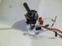
I'm afraid that it will be very difficult, as I said before, I'm poor, and only have an old scope (give me my cousin) my signal generator in the attachment.
By the moment, mi transformer designs are part of commercial amplifiers that I design and build for customers, only by request, and still are under "commercial secret", only I can assure you that they measure and sound amazingly good, but I have no digital camera to prove it.
PS. I have a plenty of literature covering this subject which I can share, but it almost entirely in Russian.
No problem with Russian, I use Google translator, and I have a Russian friend in the forum, just in case...
Thanks again!
P.S. Sorry for the low resolution photo, taken with my webcam.
Attachments
Hi !
and only have an old scope (give me my cousin) my signal generator in the attachment.
No problem with Russian, I use Google translator, and I have a Russian friend in the forum, just in case...
If your generator can top at least 100-150KHz (better up to 200KHz of course) its OK for the first time. On the scope you can check voltage peaks and dips. Cheap digital voltmeters often limited to several KHz, so in the absence of True RMS voltmeter scope is a logical choice.
BTW, many PC sound card can output up to 50KHz, use freeware ARTA as software to control frequency..
Additionally, on "Equipment & Tools" section of this forum you can ask for a simple generator schematic and prototype it on dirty cheap Chinese breadboard.
PM me with your e-mail, I'll upload Russian books on my ftp next week when will be back in the office.
If you have pc you can buy also this:
Velleman nv - International - Overview
Cheap, about €200,- and it can do a plot of your transformer if you want.
Velleman nv - International - Overview
Cheap, about €200,- and it can do a plot of your transformer if you want.
That "horizontal sectioning" is not precisely referred to the geometry. That "intermediate flange" I think is rather obvious! Popillin, I see your torment and you want to prove something where you can say I am wrong but there is no chance!
This thread remains CLOSED for me and I will not certainly tell you anymore because I don't think you deserve further explanations. As it has been re-opened you can go on forever with you logorrheic writing if you like.....without having made any transformer yet!
Even less other people that few months ago didn't know what a characteristic impedance is and now think that they make the best transformers in the world without knowing how it really works!
If your generator can top at least 100-150KHz (better up to 200KHz of course) its OK for the first time. On the scope you can check voltage peaks and dips. Cheap digital voltmeters often limited to several KHz, so in the absence of True RMS voltmeter scope is a logical choice.
BTW, many PC sound card can output up to 50KHz, use freeware ARTA as software to control frequency..
Additionally, on "Equipment & Tools" section of this forum you can ask for a simple generator schematic and prototype it on dirty cheap Chinese breadboard.
PM me with your e-mail, I'll upload Russian books on my ftp next week when will be back in the office.
I must invert a little to buy a decent Chinese function generator, my 555 based gen is a shame...
You will want to kill me, but again, my pc is an old pentium 4 build with junk, and its sound card is worse!!! No hope for me...
Thank you very much! I will send pm as soon as possible.
If you have pc you can buy also this:
Velleman nv - International - Overview
Cheap, about €200,- and it can do a plot of your transformer if you want.
Thanks a lot to you too!
€200,- is almost cheap, even for my own standards, the problem is that for now, here is forbidden import, so I must wait a change in our political...
As you can see I'm lost !
popilin: "has more than 3800 turns...0,25 mm"
Wrong design. Very high cooper losses, even for a 10 Kohm / 8 ohm trans. We DO care about cooper loss, since it is present at every level of excitation. Use a -much- larger core.
Having passed more than a week, I'm still waiting for your proof.
You also has criticized an OPT with so scarce given data
S=38x38, Np>3800, Фp=0.25 mm, Фs=0.45 mm
You said that
Zp=10KΩ Zs=8Ω
And I can say Np=3802
Ns = Np √(η Zs / Zp) = 102
ρ = R (a/l) ==> R = ρ l / a = ρ N Tl / (π r²)
Where
ρ = 0.017 (Ω mm2) / m , copper resistivity.
Tl = average turn length around bobbin in m
N = number of turns
r = wire radius in mm
For 38x38 core effective area, you need 38x43 with 0.9 stacking factor, so for that bobbin Tl≈248mm, then
Rp≈326Ω Rs≈0.338Ω
Copper losses are
Ploss [%] = 100xRp/(Zp+Rp) ≈ 3.16%
Sloss [%] = 100xRs/(Zs+Rs) ≈ 4.04%
So loss is about 0.32dB, is not to uncork champagne, but neither very high.
Obs.1-
Real world wire DC resistances are a little bit lower, because estimation supposed square turns, as winding progresses, on the edges, the wire is rounded, making correction for rounded edges, we obtain
Tl≈236mm
Rp≈311Ω Rs≈0.32Ω
Then, loss is about 0.3dB, still mediocre, but neither very high.
Obs.2-
We must consider skin effect, for a given frequency, electrons has the bad habit to travel near of wire surface.
The skin depth δ, is thus defined as the depth below the surface of the conductor at which the current density has fallen to 1/e
δ ≈ √(2 ρ / μ ω)
At 100KHz, for copper, δ≈0.23mm, so can't be go too crazy with wire diameter.
DC resistance losses isn't the whole movie...
You too Brutus?
For copper losses and frequency response, your trafo is a clear winner, but what about core losses?
I can understand that you want keep the design under secret, but I will put the things easy, can you please post only this number for your trafo?
l / (N² S)
Where
l = Lenght of the magnetic path
N = Number of primary turns
S = Cross-sectional area of the core
Just the result in [1/cm]
Thanks
ok, for a 10k just good enough but a 3,5k Ohm transformer should have some lower dc values.
I think mine has 48 Ohm and 0,15 Ohm.
For copper losses and frequency response, your trafo is a clear winner, but what about core losses?
I can understand that you want keep the design under secret, but I will put the things easy, can you please post only this number for your trafo?
l / (N² S)
Where
l = Lenght of the magnetic path
N = Number of primary turns
S = Cross-sectional area of the core
Just the result in [1/cm]
Thanks
My core is a SG108/51. Core material is HiB 0,23mm with 0,85W/kg core loss.
It has 15,32cm^2 core area and magnetic path is 25,9cm.
About 1860 windings for the primairy wire.
It has 15,32cm^2 core area and magnetic path is 25,9cm.
About 1860 windings for the primairy wire.
You too Brutus?
For copper losses and frequency response, your trafo is a clear winner, but what about core losses?
I can understand that you want keep the design under secret, but I will put the things easy, can you please post only this number for your trafo?
l / (N² S)
Where
l = Lenght of the magnetic path
N = Number of primary turns
S = Cross-sectional area of the core
Just the result in [1/cm]
Thanks
My core is a SG108/51. Core material is HiB 0,23mm with 0,85W/kg core loss.
It has 15,32cm^2 core area and magnetic path is 25,9cm.
About 1860 windings for the primairy wire.
Can I assume that you use double C and must double that area ?
Edit: There is something wrong with your numbers, doesn't match with specs
Last edited:
No, not double it. I already give the right area.
What do you think is wrong?
What do you think is wrong?
Can I assume that you use double C and must double that area ?
The transformer is a single ended double HiB c-core 3500 Ohm / 8 Ohm 60mA-120mA 30W at 18Hz.
My core is a SG108/51. Core material is HiB 0,23mm with 0,85W/kg core loss.
It has 15,32cm^2 core area and magnetic path is 25,9cm.
About 1860 windings for the primairy wire.
No, not double it. I already give the right area.
What do you think is wrong?
Bac(max) = Uac x 10⁸ / (√2 π fo S N) ≈ 14218 Gauss ≈ 14.2 T
Sorry, nothing wrong, just I thought that Bac(max) is too high, but is OK.
Remember that it depends on the airgap. It is a SE transformer
Bac(max) = Uac x 10⁸ / (√2 π fo S N) ≈ 14218 Gauss ≈ 14.2 T
Sorry, nothing wrong, just I thought that Bac(max) is too high, but is OK.
Last edited:
Remember that it depends on the airgap. It is a SE transformer
No, Bdc depends on the airgap
Bdc = 4 π μ N idc / (9 l)
μ(effective) = (l μ) / (l + le μ)
Where:
le = Airgap in cm
If Bdc depends on the airgap then Bac also depends on the airgap. You have to know what the relative permeability is.
With what permeabilty you calculate?
With what permeabilty you calculate?
No, Bdc depends on the airgap
Bdc = 4 π μ N idc / (9 l)
μ(effective) = (l μ) / (l + le μ)
Where:
le = Airgap in cm
Last edited:
Remember that it depends on the airgap. It is a SE transformer
Bac does not depend on the gap, to make it simple is proportional to the RMS signal x 10^8 and inversely proportional to the form factor (4.44 for sinusoidal signal), the frequency, the number of turns and the effective (there is a stacking factor) core sectional area.
14200 Gauss is correct but it is equal to 1.42T. So your Bdc @70mA is about 0.58 T and with those core specs I don't believe you have 30H. It is quite less than that....I could bet the Tango FC30-3.5 that you were criticizing in the first place is better than yours at low frequency.
- Status
- Not open for further replies.
- Home
- Amplifiers
- Tubes / Valves
- transformer test