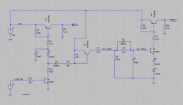
Here's a circuit I've been playing around with in LT Spice.
I'm building several channels of Pass F5 amplifier, and wanted to avoid the HUGE surge current when these things are powered on - I know dimming the house lights when you switch your system on is kinda impressive, but it just can't be good for the amp?? Also I will have 2 or 3 of these in an active setup, so triple the power-on surge and you know.. circuit breakers tripping..
So this circuit is intended to sequence two power relays for power supply inrush current limiting.
There is an auxilliary 24VDC supply which is always on and powers this circuit. When the amplifier is off, the power drain should be negligible.
Relay 1 switches 230VAC to the transformer primary. I wanted to have a remote 12V trigger input, so several amplifiers can be powered on/off in sequence. In the schematic, V2 is the control voltage, and Q5 will be replaced with an opto-coupler.
The power transformer has a nominally 120 ohm wirewound resistor in series with its primary winding. This limits the power-on surge current while the large capacitor bank on the secondary side charges up.
After 2 seconds, Relay 2 switches on, shorting across the wirewound resistor thereby directly connecting the power transformer to the mains.
Here's how it works:
Power On:
---------
Initially the remote trigger is OFF, and transistors Q1, Q4 are OFF. Both relays are unpowered.
When the remote trigger switches ON, it turns on Q5 which pull the bases of Q1 and Q2 low.
Q2 switches on immediately, and starts charging the RC time constant on the base of Q3.
Q1 switches on within 100mS, as delay capacitor C1 discharges.
Q3 has a couple of diodes connected between its emitter and ground. This raises the Q3 turn-on voltage by two diode drops - from about 0.6V to about 2V. This helps during the switch off phase.
After about 2 seconds, Q3 switches on, pulling the base of Q4 low, which switches Q4 on and powers relay RLY2
Power Off:
----------
The remote trigger goes OFF, switching off Q5.
No more current is pulled from the base of Q2 so it switches OFF.
The RC time constant on Q3 discharges via D3 and R8 within 100mS, and relay RLY2 drops out. The amplifier's power transformer is now connected to the mains via the 120 ohm wirewound resistor.
Q1 does not switch off immediately - C1 is still discharged, so it holds the base of Q1 low via R2.
After about 2 seconds, C1 has charged up enough that Q1 switches off and relay RLY1 drops out.
To do:
There may be a power-on glitch when you first connect the system to mains power. When power is first applied, C1 is discharged. I suspect this might cause relay RLY1 to 'tick' briefly. Need to sort this out before breadboarding..
Then do a PCB..")
I'm building several channels of Pass F5 amplifier, and wanted to avoid the HUGE surge current when these things are powered on - I know dimming the house lights when you switch your system on is kinda impressive, but it just can't be good for the amp?? Also I will have 2 or 3 of these in an active setup, so triple the power-on surge and you know.. circuit breakers tripping..
So this circuit is intended to sequence two power relays for power supply inrush current limiting.
There is an auxilliary 24VDC supply which is always on and powers this circuit. When the amplifier is off, the power drain should be negligible.
Relay 1 switches 230VAC to the transformer primary. I wanted to have a remote 12V trigger input, so several amplifiers can be powered on/off in sequence. In the schematic, V2 is the control voltage, and Q5 will be replaced with an opto-coupler.
The power transformer has a nominally 120 ohm wirewound resistor in series with its primary winding. This limits the power-on surge current while the large capacitor bank on the secondary side charges up.
After 2 seconds, Relay 2 switches on, shorting across the wirewound resistor thereby directly connecting the power transformer to the mains.
Here's how it works:
Power On:
---------
Initially the remote trigger is OFF, and transistors Q1, Q4 are OFF. Both relays are unpowered.
When the remote trigger switches ON, it turns on Q5 which pull the bases of Q1 and Q2 low.
Q2 switches on immediately, and starts charging the RC time constant on the base of Q3.
Q1 switches on within 100mS, as delay capacitor C1 discharges.
Q3 has a couple of diodes connected between its emitter and ground. This raises the Q3 turn-on voltage by two diode drops - from about 0.6V to about 2V. This helps during the switch off phase.
After about 2 seconds, Q3 switches on, pulling the base of Q4 low, which switches Q4 on and powers relay RLY2
Power Off:
----------
The remote trigger goes OFF, switching off Q5.
No more current is pulled from the base of Q2 so it switches OFF.
The RC time constant on Q3 discharges via D3 and R8 within 100mS, and relay RLY2 drops out. The amplifier's power transformer is now connected to the mains via the 120 ohm wirewound resistor.
Q1 does not switch off immediately - C1 is still discharged, so it holds the base of Q1 low via R2.
After about 2 seconds, C1 has charged up enough that Q1 switches off and relay RLY1 drops out.
To do:
There may be a power-on glitch when you first connect the system to mains power. When power is first applied, C1 is discharged. I suspect this might cause relay RLY1 to 'tick' briefly. Need to sort this out before breadboarding..
Then do a PCB..
Attachments
So much easier if you simply use a in-rush limiting thermister. It does the job and cost less than two bucks.
These little things are (about) 100 or 200 ohm resisters when the circuit is off and then slowly over several seconds lower to about 2 ohms. they are designed exactly for soft starts in high current devices. I got about 2 dozen of them as free samples. They came in all power ratings and time constants.
You can place one in series with the fuse on the primary side of the PT and/or on the secondary side.
Think of them as automatically controlled variable resistors.
Last edited:
Yes, the Power Thermistor is a very good solution, but it must be bypassed before it gets too hot, ready for the next restart.The major problem with the thermistor solution, which is otherwise very elegant, is what happens on multiple rapid power cycles?
The thermistor cool-down time is too long.
A relay solution should be designed for an instant disconnect and very rapid re-arm.
The auto fault clearing switches on the UK mains can try to re-establish the mains voltage every one to three seconds for two to four attempts before finally cutting off the power. I wish we could get the real info from a "Power" engineer/technician in the UK.
Last edited:
nope
You get a real el cheapo 200 to 500mA 9V AC transformer. This feeds the power to to the lm555 which after x time (I used 100ms) switches on relay 2 which bridges the resistor.
In my current amp i have 2 relays and 2 power inputs.
power input 1 = MAIN high wattage power input for 500va toroidal.
power input 2 = low wattage 220V input feeding small 9V transformer. This is fed from my surround sound processor aux output.
An extra, non audio, transformer used to power all the other circuits that can be optionally used in a Power Amplifier is a good addition.
It is cheap and it is small and it is light and generally it keeps some extra interference out of the audio PSU.
But it is not zero cost. Some will do anything "on the cheap" irrespective of what it does or doesn't do for the quality of the audio.
It is cheap and it is small and it is light and generally it keeps some extra interference out of the audio PSU.
But it is not zero cost. Some will do anything "on the cheap" irrespective of what it does or doesn't do for the quality of the audio.
What i am getting at is:
In the above circuit 3 x mje350 comes VERY close to the cost of a small 9V transformer.
other than that you need
lm555 dip ic
small bridge rectifier
220uF capacitor (should be enough you might have to experiment)
a few 1n4007 for the relay back emf
and around 1uF and 22K (i think) for the 100ms timer.
We use a very simple technique in servicing equipment. Put a light bulb in series with the power. The bulb "absorbs" the inrush. When the bulb dims, flip another switch that shorts across the bulb...You could use a multi-position switch to have a "standby" mode, followed by "ON".
I think you have overlooked the fact that there are two separate mechanisms at work here and both need addressing...................
The power transformer has a nominally 120 ohm wirewound resistor in series with its primary winding. This limits the power-on surge current while the large capacitor bank on the secondary side charges up.
They happen over very different time periods and I believe that two separate systems should be used to control the peak currents due to the different phenomena.
At start up the transformer core has no or little flux in it. This results in a very short term current into the primary of the transformer to establish the core flux. This is all complete in a few cycles of the mains waveform. Since each cycle lasts 17ms or 20ms, the system should be done with and bypassed at about 100ms to 300ms.
This is the soft start that all transformers and motors need if we are to avoid the typical starting fuse rating of ~3times the maximum rated transformer current.
480VA on 240Vac is 2Aac. The normal fuse without a soft start is ~6A. typically we use T4A, or T5A or T6A.
If we use a soft start system then that starting fuse can be reduced by a factor of three. Say between T1.6A to T2A for a 480VA 220/240Vac transformer.
When you have an auxiliary supply I would suggest a properly timed delay using a timer IC (555 are cheap and easy) of 100ms to 250ms to power a rely that bypasses the current reducer after the flux has been established.
You can use a combination of Power Resistors and/or Power Thermistors.
A 120r Power Resistor on the mains side of the Primary will get hot very quickly!!!
The second reason for high current soon after the transformer starts up is the charging of the smoothing capacitance. This happens over a period of hundreds of milliseconds to many seconds. The lower the current limit, the longer it will take.
I believe this second current surge is best met by a slow charge system timed to bypass after 1s to 10s depending on charge rate and limiting method.
Again an IC timer is better for controlled delay.
This slow charge current limiting can be done on either the primary or secondary of the transformer. I have never needed it, but my biggest capacitor bank is only +-75mF and it does not blow the close rated starting fuse (T4A for 1000VA).
If resistors are used then as soon as the resistor is bypassed the current rises instantaneously to complete the charging process. If this resistor is in the primary it will overheat. Don't.
If the resistor is in the secondary then I'd suggest that the resistor be progressively reduced over an extended period to avoid that third current peak after bypassing the slow charge.
If you choose to use Power Thermistors for slow charge, (I believe PTC are ideal for this duty) then they can be fitted in either the Primary or the secondary. Again they must be bypassed but in this case the resistance falls as the Thermistor heats during the charge build up and then the Thermistor resistance value increases again as the caps reach full charge. The current surge on bypassing is much less then with resistors. You can use longer delays here without overheating consequences. One CL60 on the 220/240primary will not do enough to allow reducing the fuse to close rated. Two series connected might just about let the fuse survive, But I suspect some experimentation will be required, particularly if you combine the soft start with the slow charge and try to do the whole current limiting with one timed delay system.
Sorry, this took so long, but there are many on the Forum who do not agree with me. As a result, I see alternative views on why and how to implement soft start and slow charge. Some are OK, some are plain dangerous. Read carefully, select what you want to believe, convince your self that what you adopt is safe and meets your criteria for performance. Good luck.
Last edited:
Would this meet your criteria Andrew;
soft start module
Soft Start Module for Mains Supply
* SSM1
* PCB
* Order Now
SSM1 Avondale Audio soft start module
Fully Automatic Timing Sequence - No more dimming lights, pops, clicks or blown fuses!
Operates in line fully automatically or manually with a low current switch.
Handles up to 1KW.
Includes an on-board mains current breaker / fuse, spark suppression and transient clamping.
Hi AndrewT,
Thanks for your very detailed thoughts on soft-start. Yes I did overlook the transformer core issue, and your ideas about PTC on the secondary side are interesting too - I'll have to take this offline and have a think.
Tangmonster - Thanks for your suggestion of using a 555 timer. I've actually done this in the past, but I was trying to achieve a discrete design, purely because I want to use parts I already have in stock. I have a large supply of MJE350's and plenty of 24V relays, so that's why my circuit uses '24V logic'.
Andrew, I agree with your comments about using an auxilliary supply for the 'other functions' in an amp, thereby keeping the main audio supply clean(er).. Apart from the external 12V trigger, there will be some (tasteful I might add) LED lighting, possibly a fan, and definitely a thermal cut-out in case of the ventillation getting blocked. Nice to keep this stuff separately powered for the sake of a few dollars.
-Len.
Marra, that soft start module has very little information to make a decision, and is rather expensive. Check out the one I bought: Connexelectronic
It says in the manual that you can download (before you buy) that it's good for 24A @ 110V or 20A @ 230V (RMS).
It says in the manual that you can download (before you buy) that it's good for 24A @ 110V or 20A @ 230V (RMS).
The major problem with the thermistor solution, which is otherwise very elegant, is what happens on multiple rapid power cycles?
The thermistor cool-down time is too long.
A relay solution should be designed for an instant disconnect and very rapid re-arm.
I used to think that would be a problem too but there is no in-rush on a rapid power cycle because the caps are still charged. You choose a themister to match the time constant on the bleeder resister. If you choose the parts correctly the in-rush current is always controlled.
The even older solution is a choke input power supply, then you don't have the problem so no solution is required.
Last edited:
- Status
- This old topic is closed. If you want to reopen this topic, contact a moderator using the "Report Post" button.
- Home
- Amplifiers
- Power Supplies
- Transformer soft-start with relays