Wrapping metal foil around the windings will become part of the transformer circuit.
Uncompleted turn i mean
a earthed coppershield, not fully closed turn (obviously or kaboom) in between pri and sec serves as a short to ground for any capacitve coupling pri-sec and is good practice , when necessary of course.
a gauss band , is that the same as a belly band or a full , closed copper band turn outside the windings?
a gauss band , is that the same as a belly band or a full , closed copper band turn outside the windings?
Andrew,
internal copper shields are electrostatic screens, and have the following constraints:
- must not create a shorted turn
- needs to have its ends insulated.
- must be connected to an appropriate AC return. A primary screen should be connected to either +Vdc_in or -Vdc_in (the input supply return). And a secondary screen should be connected to either Vout or 0V (its return)
[note my careful avoidance of the term "ground" - I use "protective Earth" when I mean exactly that]
- should have its connection in the center (lowest impedance from either end)
- must be very thin (to minimise eddy current losses)
- must have high resistivity (to minimise eddy current losses)
- needs a low inductance connection - the interconnect inductance controls the HF behaviour of the shield. this is true of all shields, be they internal electrostatic shields or external belly bands. long skinny wires pretty much ruin shields.
one cute trick for a foil winding is to add one extra turn after the DC end (usually 0V) as a shield with a free interconnect. its very easy to do, but may increase shield losses because the foil is invariably a lot thicker than a separate shield could be, and the shield connection is highly asymmetric. on the plus side its really, really easy to do.
A Gauss Band, or belly band, or flux shield has an entirely different set of constraints. Unlike an internal E-screen which is fully immersed in the transformer flux, a belly band is loosely coupled - its only the leakage flux that cuts it, and that ought to be fairly small.
so no matter how thick you make your belly band, you have almost no influence on the transformer operation at all (which is what we expect) - or to look at it another way, the eddy currents that leakage flux causes in a belly band are pretty much constant. its loosely coupled, so behaves like an independant current source.
So to minimise losses in belly band, you need to:
- form a closed loop
- use thick shield material
- use conductive sheet material (these two minimise I^2R by minimising R)
all three of which are the exact opposite of an internal electrostatic screen.
it also needs:
- to be insulated (thats an electrical safety thing, it wraps around the xfmr so gets close to pri and sec and core)
- to have a low inductance connection to a suitable AC return (I have used both -Vdc and 0V in different designs, for reasons of convenience)
a belly band can also be used to connect the core itself to some convenient AC return.
thanks!
skin depth in Copper at 50Hz is ~ 10mm, so 2 inch thick copper boxes ought to work.....
I've never used mumetal, but IIRC its also very fragile - a good whack can drop its permeability significantly.
I did find this convenient formula for low-frequency shielding effectiveness though:
SE_LF = 20*log(1 + 0.5*u_r*t/r) dB
u_r = relative permeability of shield material
t = thickness of shield material
r = distance from field source to material
FWIW
internal copper shields are electrostatic screens, and have the following constraints:
...
- must be very thin (to minimise eddy current losses)
- must have high resistivity (to minimise eddy current losses)
...
Terry, why does an electrostatic shield need to minimise these losses?
Thanks
-Antonio
Antonio,
the electrostatic shield is inside the transformer, in between windings. Its purpose is to remove (in theory. in practice it can only reduce) electrostatic (capacitive) coupling. to do that it must be conductive, and connected (via a low impedance connection - thats where theory smacks head-on into practice) so a suitable "AC return" (in a smps we're talking about a node that is DC - +Vdc_in, +12V_out etc) - a node whose voltage ISNT bouncing up and down a lot (i = C*dV/dt is what its trying to stop). you've got that.
problem is, its sitting inside the main field of the transformer. in order for flux to get from one winding to the other, its got to pass through (or "cut") the shield itself.
this will generate eddy current losses in the shield - little loop currents will flow in the shield, regardless of where or even if the electrostatic shield is connected.
so the internal electrostatic shields need to be thin - if they are > five skin depths thick, they will completely block (read as: turn into heat) the field from passing through the shield. this would be bad.
this casually ignores the actual field distribution and the effect of the core, but the guts of the argument is valid.
so you use the thinnest material you possibly can get. And even better is to use a more resistive material == less conductive => skin depth is smaller for that material.
A second reason to make the electrostatic shield thin is that it makes magnetic coupling worse - not just because of eddy current losses (which reduce transferred power) but because there is now a gap between the windings. the bigger that gap is, the worse the coupling.
I like to think of internal electrostatic shields, and external flux shields, in terms of tightly and loosely coupled coils. its not the correct way to analyse them, but it is easily understandable.
Belly bands are loosely coupled, which can be modelled as a very high leakage inductance => constant current source (kinda. it is as leakage -> infinity, but its a useful approximation to make). so the losses are I^2*R_bellyband where I is constant. ergo minimum loss needs a low resistance belly band. (this is actually a reasonable approximation)
electrostatic shields are tightly coupled - so low inductance. Its completely wrong, but I've always thought of them as the dual of belly bands - tight coupling => voltage source => V^2/R_electrostatic_shield losses. therefore we need to maximise electrostatic shield resistance. Unfortunately this is an analogy not an approximation - which is obvious when you start to look for the return path from the shield "resistance" - there isnt one, the losses are caused by eddy currents.
so its a crappy analogy for the electrostatic shield. but it does make it easy to remember.
And finally re. belly bands:
be careful with externally gapped core legs - eg in a flyback transformer. almost all of the stored energy is in the gap, and a reasonable chunk of that bulges out the sides of the gap - fringing flux. just like with a winding, it can be good to space the belly band out a bit from the external gaps (eg with tape) otherwise the belly band might intercept a fair chunk of the fringing flux. one or two gap lengths is enough, and as long as the belly band is much wider than the gap it'll work very well.
personally, I never use external gaps - only ever center-leg gaps. I have to be careful about extra winding losses, but my xfmr doesnt spew flux everywhere.
Last edited:
Terry
Thanks for your detailed reply and insight.
Must warn you I am fairly slow (usually I eventually get it), so far I understand the practical aspects (spacing and increased leakeage inductance) but still confused about the shield cutting the flux.
I can see how it cuts the leakage flux but still not seeing how it cuts the core flux.
So for the sake of arguement if one assumes there is no leakage flux would the shield still have eddy currents induced?
Thanks
-Antonio
Antonio,
my pleasure.
Oh, I see. consider a single wire, in free space. the H field is a series of circles surrounding the wire, in equal amounts at any radial angle. thats the key. the H field decreases with increasing distance from the wire, out to infinity (or at least far enough that we cant measure it any more)
now lay the wire down on a flat piece of ferrite, about 5 magnetic skin depths thick (so no flux makes it out the other side of the ferrite). the H field distribution changes, but the wire is still surrounded by H field. its just on the ferrite side all of the H field has been squashed into the ferrite, rather than extending out to infinity.
but on the opposite side to the ferrite, the H field still extends out forever - in kinda mangled half-circle-ish loops.
and thats more-or-less whats happening inside the xfmr - the core doesnt pull in ALL of the winding flux, just most of it.
Anywhere within the winding volume that isnt either core or winding will be filled with air-cored flux. any of those air-cored flux volumes that are not shared with both (all) windings will be leakage flux. remember the flux falls off with distance, and so does the "sharing" of air-cored flux volumes.
Thats why bifilar winding gives the lowest leakage - the wires all share the same physical space, and all air-cored flux volumes too.
if you have two windings, one atop the other - the outside of the outer winding has flux from that winding which is not shared by the other winding. if you surround the outer winding with ferrite (eg pot core) that flux gets coupled into the core, which reduces leakage. otherwise (eg ETD core) it doesnt - and thats why non-interleaved windings have high leakage inductance.
and for a really lousy winding technique, look at many mains transformers - Primary and Secondary are often side-by-side on the core. this makes electrical isolation a breeze, but maximises leakage inductance as the two windings share far less volume - they are as far apart as it is possible to be.
you can also control the leakage inductance by deliberately spacing windings apart.
and lastly if you look in a decent (old) transformer/magnetics text (eg magnetic circuits and transformers, MIT) they show in detail how to calculate leakage inductance, and its all about calculating the not-core-or-winding volume.
HTH
so to answer your question: in order for there to be no leakage flux (perfect coupling) all you need to do is have infinitely thin conductors all occupying the exact same volume. luckily near enough is good enough - 44AWG is a nightmare, imagine how annoying infinitely thin wire would be.
and this would also require the shield to be infinitely thin - at which point its eddy current losses would indeed be zero.
Alas wires, insulation, shields, bobbins etc all conspire to fill up our transformers with space that isnt conductor, and prevent windings from occupying the same space. so there is always leakage flux.
Last edited:
Terry
You are one good explainer (love your reason for editing).
Thanks your explanation really tied it all together for me.
For whats it worth, many years ago I designed HV (and LV) low power/noise supplies. One required 10KV p-s isolation. Started with a C-I core (I think thats what there called nowadays) with p and s on opposite sides, what a nightmare. Ended up that way too, but with a pair of coupling windings against the core added.
Similarly used aluminized mylar strips (or just copper tape) for the LV torroid core shields. Lots of fun. Never went smaller than #38.
Many Thanks
-Antonio
Terry
Started with a C-I core (I think thats what there called nowadays) with p and s on opposite sides, what a nightmare. Ended up that way too, but with a pair of coupling windings against the core
Many Thanks
-Antonio
What are coupling winding’s.
PowerBob,
I put a single layer winding against the core underneath primary as well as one under the secondary. These two additional windings were connected to each other. The effect was to reduce the leakage inductance of both p and s significantly, as you can think of it as two transformers (note the p and s windings were physically spaced away from the cores to account for the HV isolation). Came up with it in desperation so I dont know if it has a real electronic term but I think I've since seen something similar.
Thanks
-Antonio
Last edited:
Antonio,
I thought thats what you meant. nicely done coming up with that solution!
I've seen them referred to as "flux-cancelling windings" in a few papers on High-Voltage pulse transformers. when the windings are concentric (they occupy a single core leg, eg center leg of E core) one is placed on the inside (closest to core) and one on the outside (farthest from core).
the two windings are connected in parallel. If the flux cutting each winding is identical then the induced voltages of each winding are identical (V = N*dFlux/dt), and no current flows. An electrical model is a pair of voltage sources with their returns connected together, and their outputs connected together through a pair of series inductors (one for each winding).
when one winding sees more flux than the other, the resulting change in induced voltage causes current to flow between the two windings. This current compensates for the flux imbalance....damn, I cant remember exactly how! I'll have to look it up.
but work it does - I've used it to good effect, but I didn't think it up - I pinched it from an old book.
This is an old thread, but people seem to know whats going on. I am about to install an isolation transformer under my workbench so I have a question about how to with it.
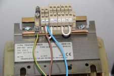
My trafo has two shields, one (primary?) between the windings. Thats SK to the left on the picture. Then it has one (secondary?) outer shield, thats SK to the right. Or is this belly band?
I now test connected the inner shield to one of the primary Vin and the outer to 0 ie the center tap of the secondary.
When i plug it this way the left 115 V winding has some 74 VAC to saftey ground and the right 115 VAC winding has some 156 VAC to saftey ground. The interconnected secondary zeros (CT) has some 40 VAC to saftey ground.
Is this the way I should do it or should I have the inner shield, the one between the windings to secondary CT and the outer shields to saftey ground?
And a follow up question on that. My plan is to let secondary (the whole workbench float. I was thinking to use secondary CT as virtual saftey ground. But that now has 40 VAC on it.
Opinions?
Attachments
the interwinding screen is intended to shunt interference to Earth.
It can only do that via a low impedance connection to Earth.
That low impedance connection is the enclosing metal chassis. It is capacitively connected to Earth.
Connect the interwinding screen to the chassis of the enclosing metal box.
Connect the metal box to PE. Low frequency interference will choose whether it goes via the capacitance, or via the inductive PE wire.
If there is a belly band, then that does not connect to anything. It floats.
If there is a second interwinding screen, then this was discussed briefly in another Thread. I don't know where the second screen should go.
But if some interference does get shunted down it's connecting wire, then that wire does not get connected to any signal ground.
It might go to the next enclosing metal box to be shunted to Earth, but that's just a guess.
Last edited:
Hi Andrew
No metal boxes around. Its gonna stand behind my workbench.
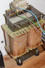
So Interwinding screen to PE in the wall, ie same as the core? External screen, around windings to nothing, just float?
How do I do with saftey grounding on workbench? I dont want mains PE there preferably.
No metal boxes around. Its gonna stand behind my workbench.
So Interwinding screen to PE in the wall, ie same as the core? External screen, around windings to nothing, just float?
How do I do with saftey grounding on workbench? I dont want mains PE there preferably.
Attachments
- Status
- This old topic is closed. If you want to reopen this topic, contact a moderator using the "Report Post" button.
- Home
- Amplifiers
- Power Supplies
- Transformer shielding