One month later...")
Here are the readings
Measure the resistance from Speaker Terminals to PE.
Measure the RCA input barrels to Chassis.
They ALL measure open circuit.
Measure the three plug top pins to Speaker terminal resistances.*
I'm not sure what you mean by this
Measure RCA barrel L to R.
Measure Speaker return L to R.
They should be <0r05
0r02/3
Measure RCA barrel to Speaker Return terminal.*
Depending on how you have connected Signal Ground to Power Ground you will get different results.
The results appear to be the same 0r02
I am going to try running a short piece of wire from the power ground to a floating star point, and then run the speaker return wire from speaker terminal to the new star point, rather than from the amp pcb. The new star will then connect to the CL60 as before
i did some measurements as well,
with the rca inputs connected and the ground to PE connection removed (chassis still connected to PE) my readings are:
speaker terminals to PE - open circuit
RCA input barrels to chassis - open circuit
Live, Neutral and PE pins to speaker terminals - open circuit
RCA barrel L to R - 0.2 ohm
Speaker return L to R - 0.2 ohm (goes open circuit when rcas are disconnected. the only connection between l and r grounds is at the preamp where the rca grounds are joined together)
RCA barrel to speaker return on the same channel - 0.2 ohm (the rca ground wire goes from the barrel to the speaker return, and one wire goes from there to the pcb, where the 0v rail is connected)
i'm stumped and considering ripping the whole thing apart and building it as 2 monoblocs
cheers,
mymindinside
Hi
Its a shame you haven't made any progress.
When Andrew mentioned the three pin connector, the IEC power inlet did cross my mind, but I didn't measure it. I also didn't have anything connected to the RCA input. I'll try measuring this too.
*I wont try rerouting my speaker returns to the new star ground point (previous post) if you don't think it will help.
Last edited:
Hi,
The problem seems to remain a mystery.
routing the speaker return away from the power ground didnt help me
i was really hoping to find a silly mistake like one of the pcb standoffs not being isolated and accidentally creating a loop but i couldnt find any.
i tried to run the both channels with one channel's PSU but the rail voltage on the loaded channel dropped to 6v and the unloaded channel rose to 36v! is this normal? my transformer is 625VA total with twin 0-18 secondary wirings. if i use only one secondary i get a roughly 300VA total (150VA/channel) i know this is less than recommended but is the draw high enough to pull the voltage down to 6v?
a niggling doubt i have is that i have connected the secondaries wrong by pairing the 4 secondary wires wrong (one winding's start wire and the other's end wire going to one rectifier). would i get any working voltage if this was the case?
cheers,
mymindinside
Last edited:
transformer blues
I investigated my transformer today (2x 0-18 - 625VA. 230v primary). the process left me as confused as ever.
The secondary side of the transformer has 4 wires coming out of it - from left to right they are black (marked 0v), blue (marked 18v), black (marked 0v) and blue (marked 18v)
i had them wired with the outer two going to one rectifier and the inner pair going to the other. when i read the voltage between these pairs it gave me 17.7v so i thought it was normal and wired it up.
after taking the amp apart today i measured the resistance between these pairs (one blue and one black wire) and it measured open circuit. i then measured the resistance between the two black wires. it measured 0.2 ohms. the resistance between the two blue wires was also 0.2 ohms. i then paired the two black wires together and the two blue wires together and measured the voltage. i got 18v from each pair!
this left me a bit confused, so i have decided not to re-connect the transformer to the rectifier before i get some advice.
to recap, i am getting 18v(approx) with two configurations. one is with the inner wires as one pair and the outer wires as the other. in this case there is one blue and one black wire per pair and it seems to be logical that this was how the transformer was meant to be wired. it is labelled this way.
the other configuration is if both the black (marked 0v) wires are one pair and the blue (marked 18v) wires are another. this configuration also gives a resistance of 0.2 ohms while the first one reads open circuit
i am thoroughly confused...please help!
cheers,
mymindinside
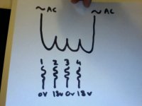
From left to right, 1/2/3/4 being wire numbers, it would seem you are saying that 1/4 and 2/3 are valid pairs which you had connected and are getting 18V readings from, and so are 1/3 and 2/4, which you have now measured and are also finding voltages at. Also, that each pair of 1/2 and 3/4 are open circuit.
Obviously, there is some voodoo at work, because if you draw this out, you will see that if 1 is connected to 2 as well as 3, then 2 is connected also to 3 and cannot measure open circuit.
It's extremely confusing, can you prepare a sketch with resistance and voltage readings?
Obviously, there is some voodoo at work, because if you draw this out, you will see that if 1 is connected to 2 as well as 3, then 2 is connected also to 3 and cannot measure open circuit.
It's extremely confusing, can you prepare a sketch with resistance and voltage readings?
Hi sangram, thanks for stepping in.
1 and 3 are black and are marked 0v
2 and 4 are blue and are marked 18v
1 and 2 measure open circuit
3 and 4 measure open circuit
1 and 3 measure 18v and 0.2 ohms
1 and 4 measure 17.7v and i cant get a resistance reading
2 and 3 measure 17.7v and i cant get a resistance reading
2 and 4 measure 18v and 0.2 ohms
1 does not appear to be connected to 2
3 does not appear to be connected to 4
i will try and post a diagram
thanks
mymindinside
Last edited:
When you say you can't get a reading, is it open circuit with the power disconnected?
It would appear to me that the correct pairs are the two black wires and the two blue wires. In most toroids, the secondary windings usually have the same colour wire for the beginning and the end of the winding to prevent confusion, it would appear a simple case of mislabelling.
I still can't get how you are managing to read a voltage off an apparently open circuit...
Hi,
when i say open circuit (1 and 2, 3 and 4) i mean that there is no resistance reading or voltage reading when these are paired together.
i too find it strange that im getting a voltage reading (1 and 4, 2 and 3) with no resistance reading. i check resistance with the power off and voltage with power on (obviously)
do you think i should connect the same colored pairs to the rectifiers and see what dc voltage i get?
cheers,
mymindinside
p.s. could this be a symptom of some kind of transformer damage? the dc voltage withe 1 and 4, 2 and 3 as pairs is about 23v unloaded and it drops to 19v with the F2 amp load. the amp sounds great with only one channel input connected. if i connect both the inputs i get a loud hum through the speakers (that is the basic problem i'm trying to resolve)
Last edited:
Now I'm more confused - you said you get 17.7V between 1/2 and 3/4 pairs.
Anyway, you should hook up the same wire colours as pairs if you're getting the correct voltage readings. Whatever your no-load reading is, you can expect it to drop a few volts when you connect two channels of the amp.
The loud hum may have been due to the return currents not being able to go back to the transformer windings, though a star ground should have been able to prevent that. Or it was working as a set of half-wave rectifiers because the transformer was only partially connected? I'm not really sure, give it a try and see what happens.
FIRST.
no power.
Use a continuity tester or the lowest scale of ohms tester.
Find which tappings are on the same winding.
If any measure open circuit they are on a different winding. But check that the enamel insulation is not giving a false open circuit.
Label the windings, A, B, C etc.
SECOND.
insert the tappings of winding A into adjacent receptacles of an insulated terminal strip.
Insert the tappings of winding B into adjacent receptacles of an adjacent terminal strip.
THIRD.
power up using a bulb tester. Just in case you have mis-wired the primary.
FOURTH.
measure the voltage of the tappings on winding A.
do the same for each of the other windings.
Switch off or better, unplug from mains.
Do not measure the voltage between different windings. They are capacitively coupled and as soon as you load them the voltage changes due to the enormous impedance of the capacitive coupling. Ignore these misleading voltages.
FIFTH.
connect bridge rectifier AC terminals to winding A.
connect second bridge rectifier AC terminals to winding B.
SIXTH.
power up through the bulb tester.
measure the voltage across the AC terminals of the bridge rectifiers.
unplug.
SEVENTH.
connect smoothing capacitor across the + & - bridge rectifier terminals.
connect the other smoothing capacitor across the second bridge rectifier terminals.
EIGHT.
power up through the bulb tester.
measure the DC voltage across each smoothing capacitor.
Check the AC voltage across the AC terminals of the bridge rectifiers.
If the bulb stays off for all these tests then you have successfully wired up the PSU.
Last edited:
when working with mains voltage.Now I'm more confused - I'm not really sure, give it a try and see what happens.
NEVER give anything a try. BE SURE before you power up.
That insurance comes from ALWAYS using a mains bulb tester to power up EVERY new mains powered project and again when ever you modify a mains powered project.
Sangram,
you are offering DANGEROUS advice that could injure other MEMBERS.
Stop before you are responsible for killing someone.
Last edited:
He's already tested and measured low voltage AC output and a resistance reading that indicates the secondary from the same coloured pairs Andrew, he was wondering whether to connect them to the rectifier. I never said anything about mains
The primary is a single primary. It works whichever way you connect it, unlike a dual primary transformer where obviously there is some concern with mains connections. At least that's what his drawing shows.
I do agree your method is more thorough and is advised for the first build, but this is a troubleshooting project and we're not even working on the mains side of the project, just the secondaries.
Anyway - I appreciate the concern
Last edited:
But remember that you need the mains to get a see-what-happens on the secondary.I do agree your method is more thorough and is advised for the first build, but this is a troubleshooting project and we're not even working on the mains side of the project, just the secondaries.
Hi AndrewT
i have measured the resistance and found that i have two windings. lets refer to them as A and B. both measure 18vac. attached each winding to the AC terminals of its own bridge rectifier (this is a enclosed metal can type- not discrete). The voodoo deepens. my dc voltage reading is just 17v! this is with no load just a multimeter attached to the dc outs of the rectifier to measure the voltage. shouldnt this be closer to 22-23v for 18vac on the secondary?
i appreciate your patient advice Andrew, and i think that the importance of safety cannot be over-emphasised. this is true even when troubleshooting because the tempation is to speed up things to get the equipment working again.
EDIT: im sorry i posted that without reading that i was to measure the ac voltage again after connecting the bridge rectifier.will check this and report
thanks,
mymindinside
Last edited:
It's pretty clear that the dual rectifiers are creating the current path so that two rails can exist even if the secondaries are wrongly connected. What is confusing are the voltage readings he's getting even with open secondaries (or not).
To illustrate my point, here are two diagrams that show the wiring - both will work, except in one configuration the rectifiers work in half wave mode. I strongly suspect the second method was used, but the understanding that I get from the TS is that there is a voltage measurement between the windings number 1 and 2 even when open.
I guess we need to see all voltage readings between all terminals of the transformer both when open and connected to the rectifiers. Unless we place a dead short between terminals of the same winding, I see little danger.
Andrew, thanks for the name-calling. I'll desist from posting further in this thread.
To illustrate my point, here are two diagrams that show the wiring - both will work, except in one configuration the rectifiers work in half wave mode. I strongly suspect the second method was used, but the understanding that I get from the TS is that there is a voltage measurement between the windings number 1 and 2 even when open.
An externally hosted image should be here but it was not working when we last tested it.
An externally hosted image should be here but it was not working when we last tested it.
I guess we need to see all voltage readings between all terminals of the transformer both when open and connected to the rectifiers. Unless we place a dead short between terminals of the same winding, I see little danger.
Andrew, thanks for the name-calling. I'll desist from posting further in this thread.
Last edited:
- Status
- This old topic is closed. If you want to reopen this topic, contact a moderator using the "Report Post" button.
- Home
- Amplifiers
- Pass Labs
- Transformer Screen & Signal Grounding Issues