Hi
I'm still trying to locate the source of my hum. I thought it might be worth fitting an aluminium screen around my F5 transformer. I'm not expecting it to cure the hum, but it might be beneficial.
I propose to bend a strip of 1mm thick, 10cm high aluminium around the perimeter. Do you think this will provide a good EMI screen?
Suggestions welcome!")
Hi,
For magnetic shielding I recommend using mu-metal:
Mu-metal - Wikipedia, the free encyclopedia
Good luck
A two channel amplifier must be assembled completely differently from a pair of monoblocks.
In a monoblock the Main Audio Ground to which all the return routes connect can be almost anywhere. I prefer to keep it close to the centroid of all the modules that connect to it. The Safety Earth connection from Chassis to PE is at the mains cable incomer.
The Main Audio Ground to chassis can be anywhere. It plays no role in the sound reproduction. It is a route capable of passing a few kA for a few us until the fault current blows the fuse.
In a two channel amplifier, the two Main Audio Grounds need a complete re-think. At some point the two channels connect. There is your hum.
I have never been able to make a chassis mounted monoblock quieter than an uncased test layout.
I have never been able to make a steel chassis two channel as quiet as an uncased monoblock.
That's why I spend the money on extra transformers and chassis.
I suspect the Speaker Return going to the PCB may be part of the problem. It works for a monoblock that has one Main Audio Ground. Two Speaker Returns going to two PCBs forces the Main Audio Ground to be compromised.
I think I remember you saying something along these lines in another post. I have only ever built dual mono chipamps, and never encountered hum, so this is new to me.
How do commercial manufactures deal this issue in stereo amps? Nelson?
I'm not adversed to buying another transformer, but I would obviously prefer to spend my money in other areas.
Last edited:
every tossed CRT monitor have plenty of nice sheet metal screen inside , useful for toroid shielding
Thanks ZM
I think a trip to the local tip may be in order
Last edited:
Andrew is correct.
Check out posts 1, 2, 4, 5 and 7. I think I like 7 the best and agree with Andrew.
http://www.diyaudio.com/forums/chip-amps/115698-understanding-star-grounding.html
Forget about the break resistor in the diagram you are using a thermistor which is better and safer.
Check out posts 1, 2, 4, 5 and 7. I think I like 7 the best and agree with Andrew.
http://www.diyaudio.com/forums/chip-amps/115698-understanding-star-grounding.html
Forget about the break resistor in the diagram you are using a thermistor which is better and safer.
Last edited:
I have never been able to make a chassis mounted monoblock quieter than an uncased test layout.
I have never been able to make a steel chassis two channel as quiet as an uncased monoblock.
That's why I spend the money on extra transformers and chassis.
I have also noticed this, but I am not sure why. What is your opinion on this?
Maybe all the radiated noise from the power supply gets reflected (instead of absorbed) and is bounced around internally in the case.
I wonder if putting the power supply in a separate case, would completely remove this issue. Which is what I have been planning on doing but am struggling to find the time to do it.
At one point in time I was thinking of making all of my cases out of wood (heatsinks exposed of course) and if required I would line the cases internally with aluminium foil.
However I gave up on the idea because I felt all the extra heat dissipation a full metal case gives was hard to ignore when building class a amps.
I suppose it is not to much extra effort to build both
Hi,
For magnetic shielding I recommend using mu-metal:
Mu-metal - Wikipedia, the free encyclopedia
Good luck
Magnetshield from Magnetic Field Shielding Materials
$4.50/ft - about 1.5ft for a 300VA toroid
Also consider routing your speaker grounds to a single point on the power supply board instead of individually to each amp board.
If you could heat treat your steel chassis to marstenite/osteonite temperatures all of the bends in the chassis would be annealed and the flux emitted by the various power supply components would no longer be traveling down these convenient flux tubes and re-emitting at various discontinuities. Some how these emission points always seem to be aimed right at low level sensitive circuitry.
I am not suggesting that you abandon your dual mono two channel amplifier.
Just address the grounding differently from what we know does work with a true monoblock.
You must approach the two channel amp with grounding as your uppermost priority and pay particular attention to avoiding shared current routes.
Just because I can't hit monoblock performance with my attempts at two channel does not mean it can't be done.
I am not suggesting that you abandon your dual mono two channel amplifier.
Hi Andrew
Don't worry, I didn't think you were
I'm just trying to get to the route of the problem first, so as to avoid unnecessary de-soldering on the amplifier pcbs. But of course I may need to do this in order to solve the problem. This is DIY after all!
I cant understand why I have hum and other don't, as most would have followed the same instructions.
I am looking forward this approach, but I haven't been able to find any comercial case for that. All the ones I've found have two heatsinks, one on each side, making it improper for a monoblock.most will build the F5 as a monoblock due to the heat dissipation.
Is there any dealer that has something suitable? What is people using for monoblock's cases (not including cases made from their owns)?
Hi Richard,
am following this thread since i am having a similar problem with my dual mono F2 build.
i think AndrewT has hit the nail on the head when he says that even though the supplies are seperate the grounds are connected at the input. Right now i have a star ground which has the Left and Right Input grounds Speaker returns, and one wire going to the ground track of each channel's PCB. i'm using Peter Daniel's boards. the 0v wires from the (single supply) power supply is connected directly to the ground track of each board. i am getting a buzz which goes away entirely when i disconnect the input RCA of one channel
sorry for bringing in my own problem Richard since it is another amp but i think the symptom is similar and the solution may be as well. i too have tried moving the transformer and rerouting the wires without success. Can anyone suggest a better grounding scheme?
cheers,
mymindinside
Hi Richard,
am following this thread since i am having a similar problem with my dual mono F2 build.
i think AndrewT has hit the nail on the head when he says that even though the supplies are seperate the grounds are connected at the input. Right now i have a star ground which has the Left and Right Input grounds Speaker returns, and one wire going to the ground track of each channel's PCB. i'm using Peter Daniel's boards. the 0v wires from the (single supply) power supply is connected directly to the ground track of each board. i am getting a buzz which goes away entirely when i disconnect the input RCA of one channel
sorry for bringing in my own problem Richard since it is another amp but i think the symptom is similar and the solution may be as well. i too have tried moving the transformer and rerouting the wires without success. Can anyone suggest a better grounding scheme?
cheers,
mymindinside
Hi Mymindinside
Please feel free to share the thread, that goes for anyone!
Can you post some good quality photos of your amp?
Puffin...another forum member has built a Peter Daniels F2 within the last 6 months, and he claims to have a hum free amp. He might be able to spot something you may have missed.
Regards
Last edited:
Hi,
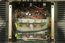
I am attaching some photos of the internals of my F2. i know it isn't neatly wired but it became messier each time i changed something to try and get rid of the hum. initially the signal grounds (input and speaker return) went to their respective pcb's where they were connected (on the pcb) to the 0v wire. the two channels were not interconnected in any way. this resulted in a very loud hum and i guessed that it was because the grounds were meeting at miniplug of the input cable (i was using an ipod source - no pre.the cable was an rca to 3.5mm miniplug which has a common ground). with this setup if i jumpered the Left and Right speaker return terminals together the hum reduced, same with the rca grounds. So i rewired it to the arrangement i described in my earlier post with a single star where the signal grounds of both channels were connected. this has reduced the hum to about 20% of what it was but it bothers me during critical listening and on quiet passages.
Is it correct to use a single star with a dual mono type amp where the channels have their independent power supplies? the 0v rails do not connect to this star but go to their respective pcb's. the star one wire connecting to each of the pcb's.
Any help will be greatly appreciated, and once again, apologies for the messy wiring.
cheers,
mymindinside
Attachments
I am having a similar problem with a Mauro Myref_c chipamp. But mine is not related to hum or ground loops (AFAIK). On my right channel I pick up a loud radio station, and less volume in the left channel. I can discern the songs and even follow them. During the day I have to put my ear next to the cone, but at night (total ambient silence) I can hear it from my listening position!
With what can it be related? My cables are shielded and give no problem with other amps. All the grounding is OK, I've already tried tying safety earth to audio ground but no difference at all. My internal wiring is quite alright, I'll post a picture if required. No crossing signal cables with outputs or psu cables, or any of them with each other.
I'll try to find what radio station frecuency I am picking.
Is the power transformer a toroid and is it sitting underneath the PCB shown at the top of the left hand photo?
If so, I agree with Nelson. Get that thing out of there or stand it on edge and place a heavy (0.060 thick) steel plate between it and the circuitry. And DO NOT run a bolt through the center hole to secure it, unless the bolt is Nylon.
If the power transformer is somewhere else, have you twisted all AC bearing wires? Do you have a full ground plane on the PCB? Are you certain that there is only one connection made to ground with all of your power and signal circuits? Have you placed a 100 ohm resistor between signal circuit ground and power circuit ground? Are you grounding to the chassis at the IEC connection to power ground?
Hi Nelson,
will move the transformer tomorrow morning and hopefully it will go away.
Budp, the transformer is below the metal plate holding the PSU caps, so will try and move it further away. it is secured by a metal bolt through the center but there is insulation(and space) between the top of the bolt and the bottom of the metal plate. Did you warn against the metal bolt because of the danger of creating a shorted turn. This is one of the things that worries me about this layout and i have ordered a nylon bolt. In the meantime do you see any danger if the insulation holds and the bolt doesnt touch the bottom of the metal plate.
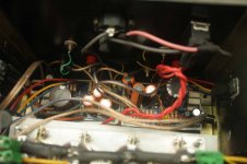
The Ac bearing wires are twisted (the primaries are the twisted red wires on the right of the 1st photo). The The two power grounds (0v rails) connect to the chassis through a CL60 thermistor each. I havent put a 100 Ohm resistor between my signal and power grounds. if i want to do this can i put this resistor between the signal star and the pcb (to which the 0v rail connects)?
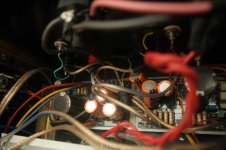
Thanks for the suggestions, and good job spotting the transformer Nelson. i had to look at the photos a few times before i saw a little edge peekng out in the third photo
cheers,
Mymindinside
will move the transformer tomorrow morning and hopefully it will go away.
Budp, the transformer is below the metal plate holding the PSU caps, so will try and move it further away. it is secured by a metal bolt through the center but there is insulation(and space) between the top of the bolt and the bottom of the metal plate. Did you warn against the metal bolt because of the danger of creating a shorted turn. This is one of the things that worries me about this layout and i have ordered a nylon bolt. In the meantime do you see any danger if the insulation holds and the bolt doesnt touch the bottom of the metal plate.
The Ac bearing wires are twisted (the primaries are the twisted red wires on the right of the 1st photo). The The two power grounds (0v rails) connect to the chassis through a CL60 thermistor each. I havent put a 100 Ohm resistor between my signal and power grounds. if i want to do this can i put this resistor between the signal star and the pcb (to which the 0v rail connects)?
Thanks for the suggestions, and good job spotting the transformer Nelson. i had to look at the photos a few times before i saw a little edge peekng out in the third photo
cheers,
Mymindinside
Last edited:
- Status
- This old topic is closed. If you want to reopen this topic, contact a moderator using the "Report Post" button.
- Home
- Amplifiers
- Pass Labs
- Transformer Screen & Signal Grounding Issues