It's pins 1 & 2, one for each channel. Pin 1 is connected to the wire link JW12 next to D1. Connect one test lead to that and the other to the speaker negative terminal
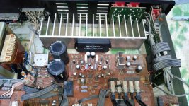
Ok. I labelled the underside in this pic (black marker and red text is me). I am going to do what you said and let you know the result.
Thanks again.
If there's a problem with the relay or something else not engaging it, should I avoid bypassing the relay for the output? Or is that too worth a check with a cheap speaker?
Attachments
You've reversed them, 6 is 1 and 3 is 2
Oh. I was just going to say... I followed the pattern printed on top of the relay. it says that's the bottom view with the numbers 6,5,4,3 in a single row. Weird.
I'll report what the offset is in a couple of mins.
Oh. I was just going to say... I followed the pattern printed on top of the relay. it says that's the bottom view with the numbers 6,5,4,3 in a single row. Weird.
I'll report what the offset is in a couple of mins.
I see what you mean, ok 3 and 6 then, the ones at either end of the four in a row
lol Yeah, I'm getting 43volts dc on pin 6. Pin 3 gives me -43 on my multi-meter.
Oh dear, that points to a catastrophic failure of the amp chip I'm afraid
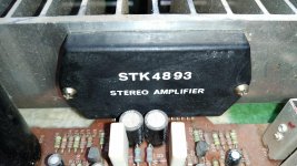
STK4893 is toast?
Have you got the volume control all the way down?
Yes.
Edit: Visually I don't notice anything. Just dirty from the previous owner.
Attachments
Last edited:
Is the amp chip warm at all?
No, but I only turned it on for the testing and then shut it off after every test.
I'll leave it on for 10-15mins or so and see. If it doesn't warm up, it's dead I assume.
I didn't realize the voltage for the relay was controlled by it. I figured something else would be responsible for that.
So if the STK4893 is toast, I'd have to find a suitable replacement. I wouldn't mind that at all, as I'm looking to upgrade the capacitors. But I'm not sure if something else caused it to fail, or if it was likely from being overdriven (I suspect).
Did you see my edit above?
The relay is driven by a chip that detects excessive offset and protects against the amp being overdriven
Sorry, yes I do have continuity between the black wire from the transformer and the negative speaker terminal. The STK chip doesn't seem to be warming up at all. Maybe it's lost contact on one of it's legs (wishful thinking lol)?
It's worth having a good look. Check you have continuity between pin 8 and the neg speaker terminal
Ok. I'll desolder it and open it up.
Pin 8 on STK has continuity with negative speaker terminal.
I didn't realise you meant opening it, why not, if it does open. The fact that it's cold is pretty decisive. The circuit diagram has a lot of voltages you could check if you feel like it, good practice for reading circuit diagram too. The negative speaker terminal is a good place to leave one test lead for measuring. I'm going to have too leave you to it now, good luck and keep me posted.
I didn't realise you meant opening it, why not, if it does open. The fact that it's cold is pretty decisive. The circuit diagram has a lot of voltages you could check if you feel like it, good practice for reading circuit diagram too. The negative speaker terminal is a good place to leave one test lead for measuring. I'm going to have too leave you to it now, good luck and keep me posted.
So... lol
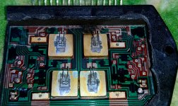
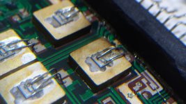
There's a small chance the burnt looking transistor still functions. Going to do some continuity testing and see if the trace is the only problem. Will report back once I confirm.
Edit: So I cleaned up the burnt area and you can tell that transistor is definitely dead. I see a tiny black spot near 1 of the 2 legs that connects it to the IC board. Guess that's that. Not sure if I should replace the IC or toss. Someone report arcing and oscillating issues when replacing STKs. :/
Attachments
Last edited:
I came across these which should be originals:
2pcs @$11.20 STK4893 Original Pulled Sanyo IC | eBay
I think I should order them and do a full recap. The amp would be a good project for me. And if I get two STKs, I'll have a backup in case something goes wrong the first time. . lol
. lol
I just have a few questions.
Aside from the capacitors, anything else in your opinion you think I should replace to be safe?
Is the amp safe to run without the STK installed? I ask because I plan on doing some more tests while I research a little more to make sure everything is as it should be. I downloaded the data sheets for this STK and the voltages we measured seems quite spot on for it. I'll do as you said and test all the voltages as per the circuit diagram.
Btw, thank you again. I've learned a lot.
Edit: I'm going to add a volume potentiometer to the list, as I'm sure it's developed static noise over the years.
2pcs @$11.20 STK4893 Original Pulled Sanyo IC | eBay
I think I should order them and do a full recap. The amp would be a good project for me. And if I get two STKs, I'll have a backup in case something goes wrong the first time.
. lolI just have a few questions.
Aside from the capacitors, anything else in your opinion you think I should replace to be safe?
Is the amp safe to run without the STK installed? I ask because I plan on doing some more tests while I research a little more to make sure everything is as it should be. I downloaded the data sheets for this STK and the voltages we measured seems quite spot on for it. I'll do as you said and test all the voltages as per the circuit diagram.
Btw, thank you again. I've learned a lot.
Edit: I'm going to add a volume potentiometer to the list, as I'm sure it's developed static noise over the years.
Last edited:
Nothing else should need replacing. It's ok to run it without the STK although the large PSU caps may hold a charge for some time, make sure they are discharged before doing any soldering or desoldering, short them with a large value (~20K) resistor if necessary. Does the relay operate with the STK removed?
- Status
- This old topic is closed. If you want to reopen this topic, contact a moderator using the "Report Post" button.
- Home
- Amplifiers
- Power Supplies
- Transformer Newbie Question