Not showing a PSRR graph is for a reason. Rule #1: Marketing is only showing best case numbers. Compare this to runtime/standby of your mobile, miles per gallon of your ride. They won't tell you worst case, especially not on the first page and in the fact summary.There's also a reason why they state this for BTL but not for SE drive.
They don't show frequency response vs distortion for the TAS5630 in the data sheet either, not because they are trying to hide anything but because they didn't include it, I have no idea why. You can see the measurements for this in the evaluation modules measurements however and its as you would expect it to be.
I would not necessarily say that TI are trying to hide anything. In fact they might be quite willing to provide you with a graph if you ask on the E2E forums. It could simply be because they haven't finished the detailed measurements for the device. After all there isn't an evaluation module available for the thing yet either.
And as to it saying its for BTL, well they have to say it's for something and most applications will use it in BTL config.
At the end of the day it doesn't matter. The amplifier will perform as the spec sheet says it will. If you want to feed it with a very noisy supply then it will have a little more influence than with some of TIs other amplifiers. It wont have any influence or impact on any designs I will build with it though.
I would not necessarily say that TI are trying to hide anything. In fact they might be quite willing to provide you with a graph if you ask on the E2E forums. It could simply be because they haven't finished the detailed measurements for the device. After all there isn't an evaluation module available for the thing yet either.
EVM will be released this month, boards is already finished and built up.
And as to it saying its for BTL, well they have to say it's for something and most applications will use it in BTL config.
Would guess many customers would like to use it in 2.1 configuration as well. SE performance will be (more) worse.
Beisde that, boards left the fab.
Attachments
Guys, there was a comment earlier on about higher distortion in SE versus BTL mode. I want to use this chip as a 2.1 for desktop speakers where the main speakers will be in SE mode, 8 ohms and typical power levels 500mW to 3W.
Looking at the graphs in the data sheet I can see the BTL has better distortion figures but not appreciably better especially for 8 ohm loads (not shown in the SE graphs but should have lower distortion than 4 ohms albeit lower power). Not sure how much of a difference this makes as I would like a high performing amp as I use quality drivers (Jordan).
SE distortion
BTL distortion
Am I wasting my time with this chip for SE mode? I *think* it should be fine....
Last edited:
Not showing a PSRR graph is for a reason. Rule #1: Marketing is only showing best case numbers. Compare this to runtime/standby of your mobile, miles per gallon of your ride. They won't tell you worst case, especially not on the first page and in the fact summary.
Edit: With forced ventilation even the actual small heatsink will be enough.
Hi Doctormod,
PSRR can be improved to 80dB at 1KHz by increasing Cstart from 10nF to 100nF. 10nF was chosen by TI to optimize pop & click in BTL mode. 100nF should still be pretty quiet, though.
Also there was some discussion about input coupling cap charging. The caps won't charge when /Reset is held low, because the AVDD regulator is disabled to save power under reset conditions. Therefore precharge happens during the 200ms after you pull /Reset high. The caps charge to around 3V through a resistance of about 3K, so you can figure out the RC time constant. About 7tau is what you need for pop-free startup. After precharge is done, input resistance reverts to the normal value.
Guys, there was a comment earlier on about higher distortion in SE versus BTL mode. I want to use this chip as a 2.1 for desktop speakers where the main speakers will be in SE mode, 8 ohms and typical power levels 500mW to 3W.
Looking at the graphs in the data sheet I can see the BTL has better distortion figures but not appreciably better especially for 8 ohm loads (not shown in the SE graphs but should have lower distortion than 4 ohms albeit lower power). Not sure how much of a difference this makes as I would like a high performing amp as I use quality drivers (Jordan).
SE distortion
BTL distortion
Am I wasting my time with this chip for SE mode? I *think* it should be fine....
Distortion is still really good in SE mode. Main issues you will face are higher noise floor and worsened low frequency PSRR. SE mode is best for satellite speakers rather than full range. Another issue with SE mode is distortion at LF caused by the output coupling Electrolytic cap. It's OK at HF. Use the BTL channel for the woofer and it should be great overall.
Current schematic (component values still aren't set yet)

And current state of the layout. Got the size down to 120x80mm, I think I'll keep it there.

Hi Gmarsh,
Thanks for publishing your design! Looks good. A couple of questions/suggestions:
* 2.1K's in series with input caps will increase noise (a tiny bit), slow the startup and reduce gain. I would recommend that they be removed.
* snubbers between switching outputs will reduce efficiency and are not needed as long as you have good close decoupling of PVDD with ceramics.
* bootstrap caps should be 33nF, not 330nF.
Thanks for the comments!Hi Gmarsh,
Thanks for publishing your design! Looks good. A couple of questions/suggestions:
* 2.1K's in series with input caps will increase noise (a tiny bit), slow the startup and reduce gain. I would recommend that they be removed.
* snubbers between switching outputs will reduce efficiency and are not needed as long as you have good close decoupling of PVDD with ceramics.
* bootstrap caps should be 33nF, not 330nF.
2.21K resistors in series: I put those there out of habit to keep the effective series resistance on the +/- terminals of the op-amp balanced minimizing input voltage offset. Which I can't do effectively as the - terminal resistance changes with gain setting, plus the OPA2134 has FET inputs, plus the amp isn't DC coupled into the TPA... so yeah, pointless having them there. I'll haul 'em out.
Snubbers: Removed from the most recent PCB design.
Bootstrap caps: Ignore the component values on the schematic, if you keep looking you'll probably find tons of other wrong values. I'll confirm all the parts values during final review.
Hi frammis, are you related to TI? I wonder what Cstart will contribute to the PSRR as its just a timing cap. Shouldn't higher values just lengthen the startup time? I also asked for this at the TI community page, but until now I haven't got an answer. Also, 3V bias voltage on the inputs is a way to low to handle 7Vpp.
Last edited:
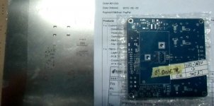
Hi doctormod,Beisde that, boards left the fab.
I've just received today my boards for 50ASX2 buffers, they where posted the 30-08-15 by Elecrow.
So shipping time was about two weeks to France.
Distortion is still really good in SE mode. Main issues you will face are higher noise floor and worsened low frequency PSRR. SE mode is best for satellite speakers rather than full range. Another issue with SE mode is distortion at LF caused by the output coupling Electrolytic cap. It's OK at HF. Use the BTL channel for the woofer and it should be great overall.
Thanks. This will be for a FAST system, SE amps will be rolled off below 150Hz with BTL for the woofer (with a LPF). Should be a good combination and allow for a very compact design. And as suggested increase Cstart to 100nF for better PSRR as suggested.
I'll knock up a schematic and PCB design with Kicad, if anyone is interested in a 2.1 amp for a FAST setup I will post here.
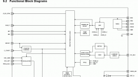
Increasing Cstart for better PSRR makes absolutely no sense to me. (From the datasheet and functional block diagram it only times startup ramp)
Hi Doctormod,
You can learn a lot from e2e. Cstart voltage tracks PVDD (try it on your board). It's the common mode input for the input stage. TI may be able to provide PSRR measurements on e2e if you ask nicely
Cstart is the input common mode? Sweet.Hi Doctormod,
You can learn a lot from e2e. Cstart voltage tracks PVDD (try it on your board). It's the common mode input for the input stage. TI may be able to provide PSRR measurements on e2e if you ask nicely
I'll use it for the Vocm of the OPA1632's, means that the input film caps don't have to charge to an offset.
Sent from my Nexus 4 using Tapatalk
Cstart is the input common mode? Sweet.
I'll use it for the Vocm of the OPA1632's, means that the input film caps don't have to charge to an offset.
Sent from my Nexus 4 using Tapatalk
Oops, sorry. Correction: It's not really the common mode. More like another input to an inverting summing amp, with a fixed reference on the + input. Therefore it can't be used to eliminate the Cin caps. Moving Cstart voltage does change the common mode DC output voltage though.
I wasn't thinking of eliminating the caps entirely, rather reducing the requirement to charge them up to 3V when the TPA starts up.
Looks like I should spend some time skimming the e2e boards.
I already did a couple of days ago and there is nothing on this there.
Oops, sorry. Correction: It's not really the common mode. More like another input to an inverting summing amp, with a fixed reference on the + input. Therefore it can't be used to eliminate the Cin caps. Moving Cstart voltage does change the common mode DC output voltage though.
But then the datasheet does not show the truth..
Would you mind to explain how this pin tracks PVCC?
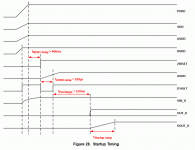
C_start (Output): Startup ramp, requires a charging capacitor to GND
isn't the "tstartup_ramp" directly relating to Cstart? If so, i don't see any PVCC relationship.
Well, i mean, if i where TI, i'd stick with the 100nF at C_start and publish 80dB PSRR. Why would i decrease the performance and try to sell this as "HD purepath"?
Hi Doctormod,
You can learn a lot from e2e. Cstart voltage tracks PVDD (try it on your board). It's the common mode input for the input stage.
Well thanks, i asked some questions at TI E2E, never got an answer.
(Beside the fact that there is actually only one thread regarding the TPA3251D2(EVM))
TI may be able to provide PSRR measurements on e2e if you ask nicely
I (normally) wont ask the vendor "nicely" to get data that is clearly missing in the datasheet. I just expect a proper datasheet with valid data.
Attachments
Last edited:
- Home
- Amplifiers
- Class D
- TPA3251d2