This is a build log of an amplifier with Bluetooth and USB, based around TPA3220 and CSR8645.
The TPA3220 is configured in stereo BTL. I used the recommended UA8014 dual inductors and film capacitors on the output LC filters.
I plan to power this from a 25V 6 cell LiPo battery, so I also have a MAX6457 voltage monitor which switches off the power if the battery voltage gets below 19.2V. Other cut-off voltages can also be selected with a jumper: 12.8V for a 4 cell LiPo or 9.6V for 3 cells.
TPA3220 has an integrated LDO which can power most of the internals of the chip if enabled, or it could be disabled in which case the chip needs an external 5V source. I decided to disable the internal LDO and provide the needed 5V from a LM1117 linear regulator. The regultator has to drop around 18V and according to the datasheet, the amp consumes around 26mA of those 5V (10mA for AVDD and 16mA for GVDD), so the voltage regulation should dissipate around 0.45W. I don't want to heat up the chip if I can help it, so I went with an external LDO and moved that heat away from the TPA3220. This probably doesn't make too much of a difference, but I will not have a heat sink on the TPA3220, and I want to drive it hard, so it can only help.
The gain of the amplifier can be set with jumpers. The chip allows: 18dB, 24dB, 30dB and 34dB.
HEAD or AD modulation can be selected with a jumper. TPA3220's reset and mute functions are also brought out to jumpers. The chip also has output signals which indicate a general fault (shorted speaker outputs) and over-temperature and clipping. These two are connected to LEDs.
The power section has a SMPS (LM2576) which brings down the battery voltage to 7V. Those 7 volts are then brought down further to 5V (for the TPA3220) and 3.3V for the Bluetooth module by two LM1117 linear regulators.
The PCB is designed with mostly through-hole components on a 10x10cm board, and it will have green soldermask, so I shall name thee: swamp thing!
I've just sent the Gerber files to the PCB fab, so I am waiting...
All the design files are open source, and can be viewed with KiCad v5. You can find the files here: NovaBox/circuit at master * nodep/NovaBox * GitHub
Thanks for reading!
Attachments

Last edited:
The prototype is working! ")
So far, I have found only one bug. I messed up the footprint of the mosfet that shuts off the circuit on low battery (I used TO-252 instead of TO-263). I fixed that on the PCB and the files.
When I first powered up the circuit, something weird happened. Bluetooth woke up nice, but the amp was outputing FAULT and turning on and off a few times a second, especially when playing music. So, I started measuring voltages with a multimeter, and noticed that the 5V output of the LM1117 was dropping to 4.5V roughly at the same time FAULT was output. I wanted to see what was going on, so I soldered wires to GND and 5V to attach the oscilloscope probes to. When I fired up the scope, everything was working perfectly! No FAULT signal, and the amp was working fine. I have no idea what happened, but I guess the 5V output of the LM1117 wasn't soldered properly to the PCB, and I inadvertently fixed that by heating up the pad to solder the wire. A bit far fetched, but that is the only thing I can come up with to explain what happened.
I haven't listened to it yet. It is late here, so I just played with it with dummy loads on the output. I have to make bigger dummy loads, my current ones can only drop 20W. With a 15V input, 4.7 Ohm / 10W resistors on the outputs, and gain set to 24dB, the chip gets up to 61 degrees C after a few minutes. The resistors get up to 220C. The over-temperature/clipping LED is almost lit all the time at this setting to signal the output is clipped.
It is getting late, so more tests tomorrow.
Thanks for reading!
Attachments

The best speakers I have are ones that came with a mid 90s CD player: Panasonic SA-CH74.
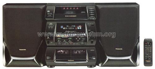
I just saw one of these things on a local auction site for 30EUR
At higher volumes they start to rattle a little. I guess a wire inside is resonating. But other than that it sounds nice. I don't have a trained ear for these things, but I am happy I wish I had access to decent speakers to really hear what this thing can sound like on good speakers.
I want to measure the THD of the amp. I guess I need an external sound card or some similar device for that, because my oscilloscope has only an 8 bit ADC. Any recommendations?
I just saw one of these things on a local auction site for 30EUR
At higher volumes they start to rattle a little. I guess a wire inside is resonating. But other than that it sounds nice. I don't have a trained ear for these things, but I am happy
I wish I had access to decent speakers to really hear what this thing can sound like on good speakers.I want to measure the THD of the amp. I guess I need an external sound card or some similar device for that, because my oscilloscope has only an 8 bit ADC. Any recommendations?
Any small 2-channel USB interfaces nowadays should be plenty for that. Stuff like Focusrite Scarlett 2i2, Presonus Audiobox, M-Audio M-track, or any other of a great number of choices.
Or if you're willing and able to spend a few minutes in order to save a few bucks, the used market is plentiful
They all have balanced line inputs, so connecting the two "ends" of a BTL output is a perfect match. You'll probably want to pad the signal down, though Pretty sure none of those would like to see more than 1-2Vrms on the inputs.
Or if you're willing and able to spend a few minutes in order to save a few bucks, the used market is plentiful
They all have balanced line inputs, so connecting the two "ends" of a BTL output is a perfect match. You'll probably want to pad the signal down, though
Pretty sure none of those would like to see more than 1-2Vrms on the inputs.I want to measure the THD of the amp. I guess I need an external sound card or some similar device for that, because my oscilloscope has only an 8 bit ADC. Any recommendations?
Thanks, but it wasn't really a matter of choice. TI recommends these, so I just went with it. It was the default optionExcellent choice of output inductors!
Any small 2-channel USB interfaces nowadays should be plenty for that. Stuff like Focusrite Scarlett 2i2, Presonus Audiobox, M-Audio M-track, or any other of a great number of choices.
Or if you're willing and able to spend a few minutes in order to save a few bucks, the used market is plentiful
Thanks a lot for these tips!
So, if I understand this correctly, I should be looking for any external card with high sample rate (96KHz, preferably) and at least 16 bit sample resolution (24 bits even better).
- Status
- This old topic is closed. If you want to reopen this topic, contact a moderator using the "Report Post" button.
- Home
- Amplifiers
- Class D
- TPA3220 based amp - swamp thing