I have 3 of the 2SC3281's which I've been testing. I tested hFE and CEO breakdown on a curve tracer and they met spec. The markings can't be removed with acetone. I installed one on a 3"x4" finned heat sink and put 20 volts at 3 amps, that's 60 watts through it. The case reached 130 degrees C. Was this a good test of power dissipation? I don't know what kind of heat sink would be required to allow 150 watts Pd.
AndrewT said:Hi,
how does a DIYer measure the capacitance of a BJT?
Method and equipment?
With the capacitance function on a DMM. Because the test frequency and amplitude may vary, expect absolute numbers to vary from meter to meter. But a real device with a large die will always have a larger Cbe than a phony so it's easy to compare a suspect to a known good unit.
Xmitr said:I have 3 of the 2SC3281's which I've been testing. I tested hFE and CEO breakdown on a curve tracer and they met spec. The markings can't be removed with acetone. I installed one on a 3"x4" finned heat sink and put 20 volts at 3 amps, that's 60 watts through it. The case reached 130 degrees C. Was this a good test of power dissipation? I don't know what kind of heat sink would be required to allow 150 watts Pd.
The same heat sink with the fins in icewater. You'll easily be able to test 100+ watts. 70V at 1.5A for one second would be a good test for a C3281. Even a 3055 could do 20V/3A at 130C case. You need to push up the voltage where a junker would go into S/B.
Thanks wg_ski, an interesting suggestion. I bit and immersed the heatsink in a tub of cool distilled water, just deep enough that the transistor wasn't wet. I put 75 watts into it and got a case temperature of 80 deg. Then I went for broke and covered the transistor too. Now I couldn't measure the case temp with my IR thermometer but figured if the water is at 25 degrees the case is too. The power derating curve shows it should handle 150 watts at 25 degrees case temp. So I hit it with 5 amps at 30 volts for a couple of minutes. The water was boiling on the transistor leads but she hung in there. After it cooled down it was still working ok. Sounds like Doc Brown in Back to the Future: "Einstein's clock is exactly one minute behind mine and still ticking!"
But an interesting experiment and looks like these Toshiba 2SC3281's are genuine.
Pretty tough little guy considering I way overdrove it with a case temp of 130 degrees at 60 watts.
But an interesting experiment and looks like these Toshiba 2SC3281's are genuine.
Pretty tough little guy considering I way overdrove it with a case temp of 130 degrees at 60 watts.
Hi,Xmitr said:I have 3 of the 2SC3281's which I've been testing. I tested hFE and CEO breakdown on a curve tracer and they met spec. The markings can't be removed with acetone. I installed one on a 3"x4" finned heat sink and put 20 volts at 3 amps, that's 60 watts through it. The case reached 130 degrees C. Was this a good test of power dissipation? I don't know what kind of heat sink would be required to allow 150 watts Pd.
with Tc = 130degC the temperature derating for a 150degC plstic package is Pmax * [(150-130)/[150-25] = Pmax * 0.16
For a 150W device operating with Tc = 130degC the power should be de-rated to 24W.
You put 60W through it.
Look up the SOA curves for the device and see where 60/0.16 lies. Use 15A and 25V (375W).
The 150 degree max junction temperature limit is mostly because the case epoxy material degrades pretty fast above that temperature. I'm not surprised it can take 60W at 130 degrees case at only 30 volts, that's just 180 degrees junction temperature.
But at higher voltages it won't take as much though...
But at higher voltages it won't take as much though...
Fakes!!! or not?
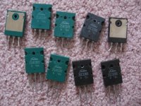
I have a bunch of Toshiba 2SC3280's and 2SA1301's that I Plan on paralleling in an amplifier, I just have no idea if they will all agree with each other when I do so...
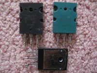
Nextly.... are these Toshiba 2SC3281's and 2SA1302 Fakes? They look genuine, will they work with the others in parallel?
I have a bunch of Toshiba 2SC3280's and 2SA1301's that I Plan on paralleling in an amplifier, I just have no idea if they will all agree with each other when I do so...
Nextly.... are these Toshiba 2SC3281's and 2SA1302 Fakes? They look genuine, will they work with the others in parallel?
Attachments
Re: Fakes!!! or not?
Don't parallel unless they're from the same batch - even if genuine.
That 1302 is suspect. Not only did they discontinue the green cases when they discontinued that script "Toshiba-san" logo, the mounting hole is too small.
CrazzyAbtTubes said:I have a bunch of Toshiba 2SC3280's and 2SA1301's that I Plan on paralleling in an amplifier, I just have no idea if they will all agree with each other when I do so...
Nextly.... are these Toshiba 2SC3281's and 2SA1302 Fakes? They look genuine, will they work with the others in parallel?
Don't parallel unless they're from the same batch - even if genuine.
That 1302 is suspect. Not only did they discontinue the green cases when they discontinued that script "Toshiba-san" logo, the mounting hole is too small.
Re: Other not fakes
I really liked those old transistors. It's a shame you can't get them anymore. I still have a few pair of C2565/A1095 in the same case. Highest freaking fT's I've ever seen in an audio power transistor - which is very good when using them above the audio range.
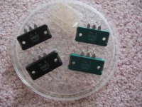
CrazzyAbtTubes said:For reference here are the 2SD845/2SB755 Toshiba outputs, these are not fakes, but the real thing, from a really good sounding LXI amplifier.
I really liked those old transistors. It's a shame you can't get them anymore. I still have a few pair of C2565/A1095 in the same case. Highest freaking fT's I've ever seen in an audio power transistor - which is very good when using them above the audio range.
Re: Re: Fakes!!! or not?
the digits rather than the "JAPAN" under the date code is suspect too. for some reason, it's more common to find PNP fakes than NPN.
there's a document you can download from the Toshiba web site. the subject is their semiconductor reliability tracking program. in there is detailed drawings of exactly what and where every inked or laser etched marking on the case belongs and what the date codes mean. unfortunately, just as with the sanken devices, it takes careful comparison to figure out the mold marks (raised letters or digits inside the dimples in the plastic) and which ones belong where. i am beginning to see a pattern with some mold marks where at least the last digit for the year is usually in one of them, and should be the same as the year mark in the printed date code.
wg_ski said:
Don't parallel unless they're from the same batch - even if genuine.
That 1302 is suspect. Not only did they discontinue the green cases when they discontinued that script "Toshiba-san" logo, the mounting hole is too small.
the digits rather than the "JAPAN" under the date code is suspect too. for some reason, it's more common to find PNP fakes than NPN.
there's a document you can download from the Toshiba web site. the subject is their semiconductor reliability tracking program. in there is detailed drawings of exactly what and where every inked or laser etched marking on the case belongs and what the date codes mean. unfortunately, just as with the sanken devices, it takes careful comparison to figure out the mold marks (raised letters or digits inside the dimples in the plastic) and which ones belong where. i am beginning to see a pattern with some mold marks where at least the last digit for the year is usually in one of them, and should be the same as the year mark in the printed date code.
Thanks for the reply, I am more used to working with tube equipment (as the name describes ) but I have decided to rebuild one of my SS amps using the Toshiba 2SA1301 and 2SC3280.
I think that I can parallel the output using the ones that have matching numbers, so the "R" going in one channel ( these were in parallel formation in another amplifier along with the fakes) And the "O" will go in the other channel ( from a cheap but working Fisher amp)
If there is anything wrong with this idea let me know, or make a seggestion...
As for the suspected fakes, they can go rott on a shelf for a while.... Maybe later I will split one open since I don't have a full set.
) but I have decided to rebuild one of my SS amps using the Toshiba 2SA1301 and 2SC3280.I think that I can parallel the output using the ones that have matching numbers, so the "R" going in one channel ( these were in parallel formation in another amplifier along with the fakes) And the "O" will go in the other channel ( from a cheap but working Fisher amp)
If there is anything wrong with this idea let me know, or make a seggestion...
As for the suspected fakes, they can go rott on a shelf for a while....
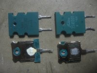
Maybe later I will split one open since I don't have a full set. Oooooooo, this is interesting, one chip is smaller than the other, and there is some white stuff on the small one!  That ain't a 100 Watt BJT!!!!!
The other one appears to have some copper pad, and has a much larger piece of silicon on it, I killed it!
Well that solves that mistery, I think when I need to find new Toshiba outputs.... I will just go to Ebay and buy some cheap SS amp such as the Fisher CA860 that the really good "O" types were found in.
That ain't a 100 Watt BJT!!!!! The other one appears to have some copper pad, and has a much larger piece of silicon on it, I killed it!
Well that solves that mistery, I think when I need to find new Toshiba outputs.... I will just go to Ebay and buy some cheap SS amp such as the Fisher CA860 that the really good "O" types were found in.
Attachments
I cracked open some ON-Semi 4281/4302 samples I had, after I blew two up in a test.
The chips inside both look similar in size to the Genuine Toshiba in your picture.
I notice the older Toshiba are rated 150W
The newer On-Semi are 230W
I wonder why they use the same size piece of silicon? Is the Toshiba underrated, or the OnSemi overrated, or does the die size matter that much with power dissipation? I couldn't help but notice how big that Toshiba transistor silicon die was.
the die size matters mostly for current density. the thermal tab (material, mass, and shape) and bonding method of the silicon die matters for heat dissipation ratings. also some dissipation ratings are calculated for a specific test heat sink, others are calculated for an "infinite" heat sink, to make it easier to calculate heat dissipation with a known finite one.
that was a nice picture. how did you accomplish separating the epoxy from the tab and die so cleanly? i made some pics where i work showing the die size of some MN2488 transistors, but i ended up with just the bottom layer of the die on the heat tab, and chunks of epoxy.
that was a nice picture. how did you accomplish separating the epoxy from the tab and die so cleanly? i made some pics where i work showing the die size of some MN2488 transistors, but i ended up with just the bottom layer of the die on the heat tab, and chunks of epoxy.
unclejed613,
nice explanation, as usual.
nice explanation, as usual.
Skilfully done for demonstration purposes. Well, those fellows have obviously not much in common, it`s not just about power handling.that was a nice picture. how did you accomplish separating the epoxy from the tab and die so cleanly?
- Status
- This old topic is closed. If you want to reopen this topic, contact a moderator using the "Report Post" button.
- Home
- Amplifiers
- Solid State
- Toshiba 2SC3281/2SA1302 - Are these fakes?