Hi Eva,
I guess you are seeing our world a little bit to negative.
And please do me one favour: Do not trust normal enamelled wire for 3...4kV. Their specified breakdown voltage depends on the wire gauge
and - yes thicker wires are specified with some kV.
BUT these breakdown voltages are specified as spot test with five probes.
Now
From these five probes one is allowed fail and the test is still passed.
...dont't touch, I would recommend...
Further on for thin the wires are not treated in a rough manufacturing site, but carefully wrapped around a 40mm ( if I remember right) cylinder. Thicker wires are twisted for the test and two times enamel is between the opposite potentials.
Even if some of your pics are not very promising, this is no reason
to damn all safety regulations.
Did you ever work with 10kV or 20kV to estimate that even this could be handled with poor isolation?
In fact I got some respect vs 10kV and more after I had
a 6 month practice in an internal isolation testing dept. for
generators at ABB.
Well, back to my PSU.
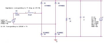
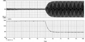
I did some simple simulation and came to the conclusion that I would need a 12V transformer, not 9V.
First the schematic of the simulation.
I guess you are seeing our world a little bit to negative.
And please do me one favour: Do not trust normal enamelled wire for 3...4kV. Their specified breakdown voltage depends on the wire gauge
and - yes thicker wires are specified with some kV.
BUT these breakdown voltages are specified as spot test with five probes.
Now
From these five probes one is allowed fail and the test is still passed.
...dont't touch, I would recommend...
Further on for thin the wires are not treated in a rough manufacturing site, but carefully wrapped around a 40mm ( if I remember right) cylinder. Thicker wires are twisted for the test and two times enamel is between the opposite potentials.
Even if some of your pics are not very promising, this is no reason
to damn all safety regulations.
Did you ever work with 10kV or 20kV to estimate that even this could be handled with poor isolation?
In fact I got some respect vs 10kV and more after I had
a 6 month practice in an internal isolation testing dept. for
generators at ABB.
Well, back to my PSU.
I did some simple simulation and came to the conclusion that I would need a 12V transformer, not 9V.
First the schematic of the simulation.
Attachments
Eva said:
Why are we not dead? We are still alive because creepage requirements are outrageous. Magnet wire enamel has usually over 3KV dielectric strenght (more like 5 or 7KV) and mylar tape also whitstands more than 3KV per layer. Furthermore, in order to start an arc between two needle shaped electrodes placed 5mm apart, more than 5KV are required, and this is the worst case, since 50KV or so would be required in order to start an arc between insulated round electrodes placed 5mm apart (like magnet wires).
I guess 15kV would do the job for two round standard enamelled wires with 5mm distance.
Eva said:
Chocoholic:
Now try to figure out how much voltage is required to get an arc between two insulated magnet wires placed 10mm apart
And even though, I'm sticking to 5mm creepage, and this already makes my transformers far safer than most ones everybody is using for audio. Then again, does tube gear dealing with 480V use 10mm creepage? No, it doesn't, and their chasis isn't even earthed!
Yes, and some other chassis are connected to mains. Depending on the direction how you insert the mains plug, you can find pretty powerful stuff on your E-guitar, whenmodifying a old radio to an guitar amp.
But that's not my goal.
BTW:
...we should not mix up creepage and clearance...
Usually the required creepages are higher than the required clearances.
Creepage requirements depend very much on cleanness stepped in three categories. For my considerations I used category 2.
Furtheron creepages depend on the surface isolation properties of
the isolation material. For my considerations I assumed the lowest CTI.
Which means the poorest comparative tracking index. With the right material you would be allowed to go for half of the creepage.
So I could search for materials with CTI>600.
Who have mixed up between clearance and creepage distance, I dont think anybody have directly done so!
Where do you find out all CTI numbers for all materials you are going to use?
Eva:
Your Nokia phone charger, the first picture shows a "thick" yellowish wire, to me it looks like a "tripple insulated wire" which, if I got it right, use to be approved in acordance with the most common electrical safety standards, these type of wires is authorized as "Reinforced Insulation" and can be used directly on primary windings without any isolation.
For instance wire from Furukawa, (for a certain diameter and type as I have noticed), the dielectrical strength is upto around 25 kV.
About demanding electrical safety standards, creepage and clearance distances, it's normaly known in free air it takes 1 mm of distance to make 1 kV to flash-over(as Eva's link shows), the much greater distances specified in many standards are due to the air will be ionized, dust covering parts that will slowly convert to carbon when theres humidity and ionized air leading to creepage currrents, and by time there will be a flash-over or lead to creeping currents that will make the equipment malfunction.
My experiences are that these problems are existing when the equipment are working in harsh environments, some have failured due to dust and humidity/condense even if these demanding creepage and clerance distance have been fullfilled due to the convertion to carbon(not to forget some galvanic/electrolytic/chemical reactions happening when theres humidity and dust) leading to creepage currents.
Though, a quite seldom problem luckely.
However, the cost to get an approval are expensive for small players, unfortunately!
Michael
Category 2 of what? Material Group... Pollution Degree.... etc etc....Creepage requirements depend very much on cleanness stepped in three categories. For my considerations I used category 2.
Where do you find out all CTI numbers for all materials you are going to use?
Eva:
Your Nokia phone charger, the first picture shows a "thick" yellowish wire, to me it looks like a "tripple insulated wire" which, if I got it right, use to be approved in acordance with the most common electrical safety standards, these type of wires is authorized as "Reinforced Insulation" and can be used directly on primary windings without any isolation.
For instance wire from Furukawa, (for a certain diameter and type as I have noticed), the dielectrical strength is upto around 25 kV.
About demanding electrical safety standards, creepage and clearance distances, it's normaly known in free air it takes 1 mm of distance to make 1 kV to flash-over(as Eva's link shows), the much greater distances specified in many standards are due to the air will be ionized, dust covering parts that will slowly convert to carbon when theres humidity and ionized air leading to creepage currrents, and by time there will be a flash-over or lead to creeping currents that will make the equipment malfunction.
My experiences are that these problems are existing when the equipment are working in harsh environments, some have failured due to dust and humidity/condense even if these demanding creepage and clerance distance have been fullfilled due to the convertion to carbon(not to forget some galvanic/electrolytic/chemical reactions happening when theres humidity and dust) leading to creepage currents.
Though, a quite seldom problem luckely.
However, the cost to get an approval are expensive for small players, unfortunately!
Michael
In my experience, that mix of ambient moisture and dust will end up creating a progressively conductive layer everywhere. No amount of clearance will solve that problem, it's only solved by properly protecting equipment against dust buildup.
Actually, approvals were invented to eliminate small players because they can grow and turn into competitors for old and well estabilished players. These costs are not fair at all but arbitrary.
That's why I'm puzzled everytime I see a 'small player' trusting and believing in approvals and safety regulations. It's like watching a small mouse heading directly to the mouth of a hungry cat (altough they are free to do that if they wish).
Chocoholic:
These regulations are not here to help you in any way or to improve safety (as the pictures show), they were made just to persuade you not to researsch, not to learn and not to develop switching equipment. And they appear to be doing their job quite well, I suppose. It's a pity, though.
However, the cost to get an approval are expensive for small players, unfortunately!
Actually, approvals were invented to eliminate small players because they can grow and turn into competitors for old and well estabilished players. These costs are not fair at all but arbitrary.
That's why I'm puzzled everytime I see a 'small player' trusting and believing in approvals and safety regulations. It's like watching a small mouse heading directly to the mouth of a hungry cat (altough they are free to do that if they wish).
Chocoholic:
These regulations are not here to help you in any way or to improve safety (as the pictures show), they were made just to persuade you not to researsch, not to learn and not to develop switching equipment. And they appear to be doing their job quite well, I suppose. It's a pity, though.
Ultima Thule said:
My experiences are that these problems are existing when the equipment are working in harsh environments, some have failured due to dust and humidity/condense even if these demanding creepage and clerance distance have been fullfilled due to the convertion to carbon(not to forget some galvanic/electrolytic/chemical reactions happening when theres humidity and dust) leading to creepage currents.
Though, a quite seldom problem luckely.
However, the cost to get an approval are expensive for small players, unfortunately!
Michael
Indeed, arcing in television sets is a problem in dusty conditions where humidity is high.
Eva, yeap, in here at finland we have those chinese pingpong atx power supplies also at market, TUKES(local authors) is withdrawing couple of models every year from market. Deer, IT-snälzth(IT-shcaisse) and Q-tec are worst **** of all time. I prefer brand names, namely Fortron-source. And yes, i have also opened my power supply, it is just fine as far as i can tell without hacksawing trafo to pieces.
Eva, I guess that your 5mm creepage is enough if your equipment is grounded, even according to some safety regulations. Double/reinforced insulation is much more demanding, as we saw from chokoholic.
Kenshin, I can confirm what others have said about those small smps units, triple insulated "abnormal looking" wire is used in them.
In my opinion, double insulation is a total overkill for high power applications. I think that power amplifiers are the piece in the audio chain that should be earthed.
On the other hand, double insulation (with as much creepages as desired) is very easy to implement in low power audio PSUs where size is not strongly limited. Any potential ground loop issue is easily solved by using differential inputs or outputs (or both) and star grounding (to force loop currents to follow a known path).
Also, I'm thinking about building my own insulation tester. I have some medium-size and big 50Hz iron-lamination cores that I can dismantle and rewind as 100:1, 200:1 or 500:1 step-up transformers (this time with gentle creepages and maybe some epoxy).
I could bet that those chinese transformers with no creepage doesn't break down until well above 5KV (there's no better way to know than testing).
Chocoholic:
I don't like your idea of stepping down mains to 12V through a conventional transformer and then stepping it up back to the voltages required by your amplifiers. It sounds bulky and quite inefficient to me.
I would prefer stepping up 12V (10..15V) to 300V (250..375V) in an unregulated way (simple, smaller and more efficient). That +300V bus may be also powered from rectified mains (skipping PFC stage since you seem not likely to enjoy the added complexity and you can't sell your equipment anyway). Bulk storage capacitors should be placed on that +300V bus (they are required for mains rectification anyway, and this already requires a lot of capacitance, furthermore 400V capacitors store more joules per euro in less space, and peak currents when using 12V power are dramatically reduced). And then, a full or half bridge regulated converter powered from the +300V bus would follow (preferably using IGBTs since their losses doesn't increase proportionally to I^2 like in MOSFETs but to I).
Hint: look for used oil burner ignition transformers, 10kV (+-5kV center-tapped). Or neon light transformers.Eva said:
Also, I'm thinking about building my own insulation tester. I have some medium-size and big 50Hz iron-lamination cores that I can dismantle and rewind as 100:1, 200:1 or 500:1 step-up transformers (this time with gentle creepages and maybe some epoxy).
mzzj said:
Hint: look for used oil burner ignition transformers, 10kV (+-5kV center-tapped). Or neon light transformers.
Could a flyback transformer work if the primary drive were adjusted to lower the voltage as needed?
Sometimes things in those piles of old parts come in handy. I have numerous previously wound toroids, e-cores, etc. and various and sundry parts which I have accumulated. It is nice being able to maintain as much momentum as possible and not be delayed when trying out design ideas.
Chocoholic, what do you use for "operating voltage" for half-bridge or flyback?
"— the actual r.m.s. or d.c. value shall be used;
— if the d.c. value is used, any superimposed ripple shall not be taken into account;"
Rms voltage of waveform at transformer primary?
And what pollution degree you use/assume?
"— the actual r.m.s. or d.c. value shall be used;
— if the d.c. value is used, any superimposed ripple shall not be taken into account;"
Rms voltage of waveform at transformer primary?
And what pollution degree you use/assume?
mzzj said:Chocoholic, what do you use for "operating voltage" for half-bridge or flyback?
"— the actual r.m.s. or d.c. value shall be used;
— if the d.c. value is used, any superimposed ripple shall not be taken into account;"
Rms voltage of waveform at transformer primary?
And what pollution degree you use/assume?
You are right.
For the flyback it would be sufficient to calculate the RMS value.
Even with the reflected voltage and leakage peak going up around 750V peak in worst case... the RMS value would remain around 450V, instead 600V that I had assumed.
For a boost topology I calculated 500V DC, as
my plans were considering a 480V DC rail.
So the isolation requirements would be pretty much the same in both topolgies .
My pollution degree was 2. Isn't that the common assumption for
non sealed indoor electronic equipment?
Eva said:
Chocoholic:
I don't like your idea of stepping down mains to 12V through a conventional transformer and then stepping it up back to the voltages required by your amplifiers. It sounds bulky and quite inefficient to me.
I would prefer stepping up 12V (10..15V) to 300V (250..375V) in an unregulated way (simple, smaller and more efficient). That +300V bus may be also powered from rectified mains (skipping PFC stage since you seem not likely to enjoy the added complexity and you can't sell your equipment anyway). Bulk storage capacitors should be placed on that +300V bus (they are required for mains rectification anyway, and this already requires a lot of capacitance, furthermore 400V capacitors store more joules per euro in less space, and peak currents when using 12V power are dramatically reduced). And then, a full or half bridge regulated converter powered from the +300V bus would follow (preferably using IGBTs since their losses doesn't increase proportionally to I^2 like in MOSFETs but to I).
I also do not really get a state of the art feeling....

But it is perfectly simple and as the heavy 12V caps are existing anyway, because of the car supply option.... A single torroid + rectifier seems to come not heavier, not bulkier... , than my set up
with boost + halfbridge + proper filtering.
I could skip the boost, you are right. And go for a halfbridge converter only. But this solution would not be perfectly simple and also not perfectly state of the art. ... and less fortunate for 120V/230V... Somewhere inbetween.... hm....
Currently none of the solutions is really giving me the kick.

From technical side the boost+halfbridge would be the best.
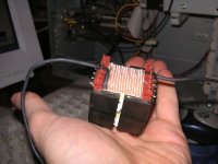
BTW: I already finished the stepped gap choke for the PFC.
Attachments
ChocoHolic said:
My pollution degree was 2. Isn't that the common assumption for
non sealed indoor electronic equipment?
Umm, guess so. Just got this standard to my hands today so I am not any sorta expert.
How about epoxy potting your trafo, then you could use pollution class 1 creepages and best CTI values?? No need for vacuum-potting tough as its only for against pollution
btw, I dont have any clue about different material CTI values because I dont have access to that xxxx standard where they are specified. Do you have this standard? I would be intrested to hear some examples.
 arrgh, would need tons of publications to cover just en60065 and its references
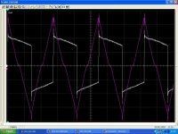
The stepped gap choke is a doubled EVD 36.
43 turns of 150x0.1 silk covered HF litz,
wound in three layers with interlayer isolation.
At low currents L=1.1mH.
At levels above 0.7A it changes to 330uH and remains stable
up to all area saturation at around 17A.
If heated to 100°C, this saturation may happen around 12A, which is
my worst case requirement at 120V.
...hm, somehow I am curious...
Attachments
- Status
- This old topic is closed. If you want to reopen this topic, contact a moderator using the "Report Post" button.
- Home
- Amplifiers
- Power Supplies
- Torroid vs. SMPS