rewire the dual polarity supply as a single polarity supply.
Now insert the output cap.
That output cap blocking DC to the speaker performs the same filtering of the bass output as the two smoothing caps do in a dual polarity supply.
It is this filtering effect that determines the inter-relation of the amplifier passband input filer to the NFB filter created by the NFB dc blocking cap and to the smoothing caps.
I have adopted the recommendation I saw on this Forum many years ago to ensure that the pass band is defined by the passive filters on the input
and that NFB RC > 1.4 times Input filter RC
and that smoothing capacitance filter RC > 1.4times NFB filter RC.
If this relationship between the RCs of the three filters does not comply, then performance is affected in the intended passband.
Last edited:
Take the DC coupled power amp running on dual supplies and scope the output across the load all the way down to DC. The amp has no LF roll off due to reservoir cap size. It goes all the way down to DC.
All the lower capacitance reservoir caps do is generate increased ripple, the troughs of which put a limit on the maximum achievable output.
A single polarity supply is slightly different. To demonstrate that you could use a very large speaker coupling cap and a low value reservoir cap. The amps lower frequency would still be determined by the speaker coupling cap and not the reservoir cap... within the limits of what the supply could deliver and the expected output of course.
Last edited:
In what way ? The PSU caps are not part of the "output circuit", there is no high pass filter formed.
Now is that true? Simulations show something els.
Nope.That output cap blocking DC to the speaker performs the same filtering of the bass output as the two smoothing caps do in a dual polarity supply.
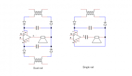
Is this what we are talking about?
Drawn a bit strangely but yes. A DC coupled speaker on the dual rail and an AC coupled speaker on the single rail.
Now take away the diode that recharge the capacitors at ~ 10% duty cycle.
The speaker in both situations is fed from the capacitors. It is an RC system.
The Power Supply capacitors affect the speaker output, a lot, at lowish frequencies and a little, at higher frequencies.
Fitting too small PSU smoothing capacitors (relative to intended passband) and it impinges on the LF performance of the amplifier.
Try outputting a full voltage DC signal and see how long it lasts before the output voltage drops. That loss of output voltage is the filter effect. The low frequency voltage cannot hold up at -0.1dB for very long, if too small capacitors are used.
Gentlemen, before we sidetrack into technical discussions that will only confuse the original poster ...
fr1s, have your questions been answered? Do you feel comfortable enough to keep moving ahead?
I commend your DIY spirit and get-your-hands-dirty attitude!
Cheers,
Jeff
PS Van City, I take it that's Vancouver. Are you getting any of this deep freeze that we're getting in Southern Ontario?
fr1s, have your questions been answered? Do you feel comfortable enough to keep moving ahead?
I commend your DIY spirit and get-your-hands-dirty attitude!
Cheers,
Jeff
PS Van City, I take it that's Vancouver. Are you getting any of this deep freeze that we're getting in Southern Ontario?
Now take away the diode that recharge the capacitors at ~ 10% duty cycle.
The speaker in both situations is fed from the capacitors. It is an RC system.
The Power Supply capacitors affect the speaker output, a lot, at lowish frequencies and a little, at higher frequencies.
Fitting too small PSU smoothing capacitors (relative to intended passband) and it impinges on the LF performance of the amplifier.
Try outputting a full voltage DC signal and see how long it lasts before the output voltage drops. That loss of output voltage is the filter effect. The low frequency voltage cannot hold up at -0.1dB for very long, if too small capacitors are used.
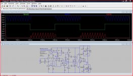
Lets try and get to the bottom of this. Here is a simulation of Dougs blameless Class B (chosen for the simple reason I had it on file). Here it is being fed with a 5hz squarewave into a four ohm load. The reservoir caps are 1000uf. The ripple on each rail is clearly shown.
The reservoir cap currents are in the second piccy. Also in red is the current in the load.
So how do the reservoir caps affect the output at LF ?
Attachments
Now is that true? Simulations show something els.
Post your sim
")
The gap between the Supply rail ripple and the output signal is predicted as ~15VLets try and get to the bottom of this. Here is a simulation of Dougs blameless Class B (chosen for the simple reason I had it on file). Here it is being fed with a 5hz squarewave into a four ohm load. The reservoir caps are 1000uf. The ripple on each rail is clearly shown.
The reservoir cap currents are in the second piccy. Also in red is the current in the load.
So how do the reservoir caps affect the output at LF ?
If this overhead is reduced by increasing the output current then eventually the 5Hz performance will be affected.
You can increase the output current by reducing the load resistance or increasing the signal level.
Now back to your assertion that you can output a DC signal.
Show the simulation for a 25Vdc signal and how long it manages to hold up at 25Vdc as the rail to signal overhead reduces.
The gap between the Supply rail ripple and the output signal is predicted as ~15V
If this overhead is reduced by increasing the output current then eventually the 5Hz performance will be affected.
You can increase the output current by reducing the load resistance or increasing the signal level.
Now back to your assertion that you can output a DC signal.
Show the simulation for a 25Vdc signal and how long it manages to hold up at 25Vdc as the rail to signal overhead reduces.
Working on a sim. Your sim looks good. Can you try it again with a higher input signal. You wil not see a problem until the output voltage reaches the rail voltage.
What I said in post #22 holds true,
http://www.diyaudio.com/forums/chip...former-question-gain-clone-2.html#post3772203
The maximum output voltage is determined by the troughs in the ripple voltage. Up to that point the output is "perfect".
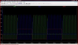
Here is a 10 second run showing the amp delivering negative 10 volts DC across 4 ohms. The negative rails ripple is huge because of the 1000uf reservoir caps. There would be no effect on the output voltage until the ripple "troughs" impinged upon it due to increasing current demands.
Andrew... can you see how the ripple current (which is huge) has no effect on the output. Similarly it is true to say that the output current, is independent of the ripple current, and in no way can a constant DC output currrent (0Hz a valid condition) can be said to be "passing through" the reservoir caps.
Edit... Red is the positive rail, green the output and blue the negative rail.
Attachments
I do agree that a capacitor cannot achieve constant DC output to the load on the amplifier.
That is the point I am making.
The PSU capacitance determines the LF performance of the amplifier and the way it can deliver current to the load.
The PSU capacitance must be capable of allowing the amplifier to work properly down to the intended passband of the amplifier. This is a equivalent to delivering power to a load from an RC limited system. The filter effect of the PSU+Load (RC) must not be narrower than the intended passband of the amplifier.
Have you looked at a 25Vdc output signal that I suggested?
Since the PSU is idling along at ~46Vdc. Try an output voltage of 35Vdc and 40Vdc.
How long can the amplifier maintain these output voltages?
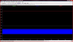
The effect will show a lot sooner than output DC reaching the rail voltage. Very much sooner. That's why I initially asked for the same sim at a 25V output signal with the supply as shown.Working on a sim. Your sim looks good. Can you try it again with a higher input signal. You wil not see a problem until the output voltage reaches the rail voltage.
Here is a sim. Load Voltage is only half the Rail Voltage.
That illustrates the point I made in post #22 You are seeing the ripple voltage impinge on the maximum output voltage.
The gain will also vary as the voltage differential drops.
i.e. it is a filter effect.
Compare the two diagrams in post25. They are so similar that you can see the RC filter.
Everyone accepts and recognises the filter imposed by the output cap in the single ended version.
That cap just moves to the other side of the Ground reference terminal in the dual polarity example. It is still an RC filter effect. If the charging system were a constant DC of appropriate impedance, we would not see the ripple imposed on the output signal, we would just see the droop in output voltage, i.e. reduced gain, as the two voltages approach each other.
I do agree that a capacitor cannot achieve constant DC output to the load on the amplifier.
That is the point I am making.
The PSU capacitance determines the LF performance of the amplifier and the way it can deliver current to the load.
The PSU capacitance must be capable of allowing the amplifier to work properly down to the intended passband of the amplifier. This is a equivalent to delivering power to a load from an RC limited system. The filter effect of the PSU+Load (RC) must not be narrower than the intended passband of the amplifier.
Have you looked at a 25Vdc output signal that I suggested?
Since the PSU is idling along at ~46Vdc. Try an output voltage of 35Vdc and 40Vdc.
How long can the amplifier maintain these output voltages?
It was what you said in post #21.... where it read (referring to a single rail amp),
"That output cap blocking DC to the speaker performs the same filtering of the bass output as the two smoothing caps do in a dual polarity supply."
And this from another post,
"the minimum smoothing capacitance depends on the pass band required from the amplifier.
As you now acknowledge, the reservoir caps have no direct influence on the pass band of the amp. Their influence shows when the amplifier output current is too great, such that the rails sag.
Its almost become part of amplifier folklore to say "the speaker is in series with the PSU caps". It isn't.
- Status
- This old topic is closed. If you want to reopen this topic, contact a moderator using the "Report Post" button.
- Home
- Amplifiers
- Chip Amps
- Toroidal transformer question [Gain Clone]