The unbalanced upper half waveform to the lower half waveform allows the core to saturate. This is the same effect as applying a small amount of DC to the AC waveform. The saturated core does not create as much back emf to resist the driving voltage and the primary current increases, sometimes massively. The increased current results in bigger forces and thus higher noise level. If you listen to a toroid that is suffering from this DC effect it "growls" rather than hums...................troystg said :
"But also sometimes DC on the mains causes a noisy transformer."
I do not understand really how it would be possible ?
It's not a power supply company issue.It would be a power company supply to house grounding issue but sadly it happens. You can measure the DC voltage on your outlets.. IDEALLY there is NONE. If there is some check the house ground and or have the power company check the feed.
I have seen it twice in my limited years, both >50 year old homes in rural areas with very old transformers from the power company.
It's the customers that create the effect.
Many customers draw off current at the top of the voltage waveform. This creates the "flat topped" sinewave we can see on the scope.
If the flat tops are not exactly symmetrical then the sinewave is not exactly symmetrical. It's the asymmetry that the transformer core sees as unbalanced upper and lower halves.
That is where my earlier post takes over.
There is no DC to measure. The waveform is AC with lot's of distortion and AC interference.
It's not a power supply company issue.
It's the customers that create the effect.
Many customers draw off current at the top of the voltage waveform. This creates the "flat topped" sinewave we can see on the scope.
If the flat tops are not exactly symmetrical then the sinewave is not exactly symmetrical. It's the asymmetry that the transformer core sees as unbalanced upper and lower halves.
That is where my earlier post takes over.
There is no DC to measure. The waveform is AC with lot's of distortion and AC interference.
Thank you for the explanation, I always thought the issue came from AC being on top of a DC voltage.
This is getting a bit off topic, but I'm very interested in the DC discussion. Like how do customers draw off current at the top more than elsewhere in the wave (other than near zero), and how does that cause a sag and flattening that isn't balanced across the sine wave? But perhaps better to continue this in a new thread if it's going to continue?
A resistor load, like an off-peak heater or an electric kettle draws current throughout the waveform. The current curve follows the voltage curve. The resistor load does not cause waveform distortion.Common sense tells me that being the top of the wave the highest voltage, it is the highest current consumption point too (at least on resistive elements, like an electric heater). That should make it the highest power consumption point.
Sorry for the OT
A capacitor input filter does cause waveform distortion.
Half wave rectified speed controllers that used to be fitted to electric drills cause waveform distortion.
SMPS before they started fitting Power Factor improvement circuits caused waveform distortion.
SMPS with PF circuits still cause waveform distortion, just less of it.
Motors cause waveform distortion.
The list is nearly endless.
A resistor load, like an off-peak heater or an electric kettle draws current throughout the waveform. The current curve follows the voltage curve. The resistor load does not cause waveform distortion.
A capacitor input filter does cause waveform distortion.
Half wave rectified speed controllers that used to be fitted to electric drills cause waveform distortion.
SMPS before they started fitting Power Factor improvement circuits caused waveform distortion.
SMPS with PF circuits still cause waveform distortion, just less of it.
Motors cause waveform distortion.
The list is nearly endless.
Yes, nearly endless. Another wave form distorter: when those motors turn on or off (like from a refrigerator or air conditioning thermostat).
Little know fact: 60+% of all electric motors just move air and gasses around ... and all most all of those turn on and off from a pressure sensor or thermostat, without regard to the power grid or the power grid wave form ... or your audio power supply.
Last edited:
New mounting..
An externally hosted image should be here but it was not working when we last tested it.
Perfect. This is exactly how you do it.
I even feel that I have more spl in low frequencies !
Not to burst your bubble, but that's probably just confirmation bias.
Judging from the rest of the posts, there still seems to be some confusion about shorted turns.
A transformer consists of a core and at least two windings. The windings are the wire that make up the primary and secondary of the transformer. Each winding has a certain number of turns, i.e. the wire goes so many turns around the core to form the winding.
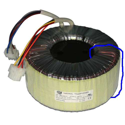
With toroidal transformers, the shorted turn comes up because improper mounting using metal hardware can form a completed turn around the cross-sectional area of the core. This forms another secondary winding consisting of one turn of conductive material. This new secondary has been short circuited. This will present a short circuit to the primary and blow the fuse. This is shown in blue in the figure below.

If you can trace metal all the way around the cross-section of the transformer core (i.e. through the donut hole), and this metal forms a conductive ring around the cross section of the core, you have a shorted turn. That is illustrated below. I've traced the shorted turn in blue.

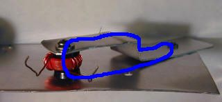
How do you avoid this: Use the proper hardware as Philfr ended up doing. This works because, although, the metal mounting bolt goes through the donut hole in the transformer, the turn is never completed. The turn starts at the top metal washer, through the bolt, into the chassis, and never returns to the top metal washer.
There's no need for nylon hardware. Nylon isn't suitable for anything related to heavy transformers as it tends to stretch.
~Tom
Tom: Excellent tech support. A solution for an important question.
Thanks for the recognition.
~Tom
Adding a metal screw at center change a little the inductance of toroid.
But it is what is important and what does it change?
Phil.
The screw does not interact with the electric field in the transformer core. The inductance doesn't change.
~Tom
I thought this because when I measure coils with and without metal screws, it changes !The inductance doesn't change.
Phil.
I thought this because when I measure coils with and without metal screws, it changes !
Phil.
If you drive a screw made from a ferromagnetic material through an inductor in parallel with the electromagnetic field, you will greatly increase the inductance of the inductor. However, in case of a toroidal transformer, the EM field is perpendicular to the screw. The screw will interact with the leakage field to some extent, which may impact the magnetizing inductance ever so slightly, but it will not have an impact on the functionality of the transformer. Now an RF torridal inductor, that may be a different story. With RF you also aren't dealing with H and mH. You're in the nH territory so a minute change matters more.
~Tom
... Judging from the rest of the posts, there still seems to be some confusion about shorted turns.
A transformer consists of a core and at least two windings. The windings are the wire that make up the primary and secondary of the transformer. Each winding has a certain number of turns, i.e. the wire goes so many turns around the core to form the winding.
With toroidal transformers, the shorted turn comes up because improper mounting using metal hardware can form a completed turn around the cross-sectional area of the core. This forms another secondary winding consisting of one turn of conductive material. This new secondary has been short circuited. This will present a short circuit to the primary and blow the fuse. This is shown in blue in the figure below.
If you can trace metal all the way around the cross-section of the transformer core (i.e. through the donut hole), and this metal forms a conductive ring around the cross section of the core, you have a shorted turn. That is illustrated below. I've traced the shorted turn in blue.
How do you avoid this: Use the proper hardware as Philfr ended up doing. This works because, although, the metal mounting bolt goes through the donut hole in the transformer, the turn is never completed. The turn starts at the top metal washer, through the bolt, into the chassis, and never returns to the top metal washer.
There's no need for nylon hardware. Nylon isn't suitable for anything related to heavy transformers as it tends to stretch.
~Tom
This is great ... Glad a moderator recognized these valuable lessons and made this a separate thread / topic.
This is deep physics, but the pictures make it all come clear ... Thanks Tom! Thanks Phil!
Before:
An externally hosted image should be here but it was not working when we last tested it.
After:
An externally hosted image should be here but it was not working when we last tested it.
Last edited:
Just curious -- Antek provides a toroidal shields made of steel:
Misc - Steel Cases - AnTek Products Corp
The shield is constructed of a thick metal post in the center and a cylindrical cover that covers the torroid but does not quite reach the bottom of the chassis to which the torroid is mounted. Meaning, the center shaft is about 3mm longer than the skirt so there is a similar gap all around. I figured this had to do with cooling, but I wonder -- the gap would seem to prevent a shorted turn as well. Is this correct?
NEVER HALFWAVE RECTIFIER A TOROIDAL TRANSFORMER.
Hi All
Toroidal transformers do not have AIR GAPS. The DC component that you see is unbalanced rectification as Tom stated.
NEVER HALFWAVE RECTIFIER A TOROIDAL TRANSFORMER.
Shorted turns are also caused if the top cover comes in contact with the mounting hardware of the toroid.
I started the Epoxy filling of toroids in the early 70’s when I was @ BGW. The next year several other mfg’s were doing the same.
Duke
I wonder -- the gap would seem to prevent a shorted turn as well. Is this correct?
Cut-n-pasted from Antek's website:
The center rod is about 0.05” longer so there is not electrical short on this case to the main chassis (assume the chassis is metal).
~Tom
I started the Epoxy filling of toroids in the early 70’s when I was @ BGW. The next year several other mfg’s were doing the same.
What prompted the epoxy filling? What benefit did it provide (aside from electrical isolation)?
~Tom
Epoxy filling of toroids
Hi Tom
You ask WHY? Shorted turn.
The top cover shorting to the mounting hardware. This caused welding the bolt to the top cover and tripping the circuit breaker.
Epoxy filled and using a counter bore the top of the bolt is below the surface of the transformer.
Best Duke
Hi Tom
You ask WHY? Shorted turn.
The top cover shorting to the mounting hardware. This caused welding the bolt to the top cover and tripping the circuit breaker.
Epoxy filled and using a counter bore the top of the bolt is below the surface of the transformer.
Best Duke
- Status
- This old topic is closed. If you want to reopen this topic, contact a moderator using the "Report Post" button.
- Home
- Amplifiers
- Chip Amps
- Toroid Transformer Mounting