Pretty darn close, with the usual caveat that Hornresp does not model upper breakup modes, and tends to exaggerate peaks and dips.Hey Art,
How close is the equivalent Hornresp model to you design? Any insight you can offer?
I'd show you the Smaart charts of my 8" drivers, but unfortunately at some point I deleted them.
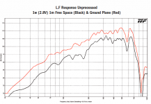
Their response was very close to the VTC eL 210 shown below, around a 10-12 dB per octave drop below Fc.
The VTC chart cuts off before all the weird out of band upper junk happens, it is not pretty, and requires PEQ to get rid of it, it is audible even using a 24 dB per octave crossover.
That said, the acoustical HP the exit ports create eliminate a lot of harmonic distortion, I have run the 8" to Xmax and they still sound pretty darn clean, much better than BR cabinets at the same excursion.
At first glance, one would think the falling LF response would not allow a 100 Hz crossover, but when a number of cabinets are used the response becomes flat.
I actually have to cut the 8" response a bit down around the crossover point when using 67.5" ( the bottom 22.5" are 8" speakers only) of mid/top cabinets.
Using bass reflex ports could allow less modules to get flat down low, but at the expense of transient response. And since one ideally would want around one wavelength, 135 inches of line for a 100 Hz crossover, and I'm only half way there, the extra cones needed to get the LF are fine.
If I were to start from scratch (I have had the HF drivers since 1992, and the 8" for a decade or so) I'd be inclined to use four 6.5" and one (or two) 1" driver per cabinet, more height per $$ and more extended HF.
Art
Attachments
Take a look at olsound top for tap.Epa design a nice top for him.
you wouldn't happen to have a link maybe?
http://www.diyaudio.com/forums/multi-way/190647-top-tap.htmlyou wouldn't happen to have a link maybe?
The side by side mid/HF arrangement that the Versarray 112 (and many other poorly designed "line array" speakers use causes non-symetrical off axis cancellation in the crossover region. The “suck out” generally occurs right in the middle of the vocal range.after reading this thread and thinking, i am thinking a single box containing a 12+1, or 12 +1+1, or 12+2, or 10+10+1+1; i think i may be rambling. i would build 3 per side and stack them. might steal peavey's mounting system for the Versarray 112.
The use of a 12 for mids requires a crossover region in the 1200 range for the mid to high dispersion to match (assuming a 90 degree -6 dB coverage is chosen) for the mid/hi sound waves to combine without comb filtering in the horizontal axis requires the center to center spacing to be within 1/4 wavelength, just under 3 inches, obviously not possible with a side by side arrangement. A higher crossover, as Peavey uses for the 112 to keep the ribbon tweeters from burning, makes the problem worse.
I’d recommend a pair of cabinets with the HF over the MF, flip the top cabinet over so the HF are together, the off axis response will be far more consistent.
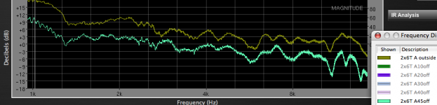
Another suggestion would be to use side plates over the mid drivers to make the dispersion match the HF horn at the crossover point, and reduce some of the upper cone breakup, an example shown below using Kappa 10” mids and a 90 x 30 conical horn.
Attachments
Last edited:
I find myself agreeing with about everything art says in the last few posts.... hmmm.....
I happen to use a 'coax' arrangement with compression driver in front of the mid to prevent 'beaming' as well as a slot the driver fires through for dispersion reasons.
http://www.diyaudio.com/forums/subwoofers/170771-single-sheet-th-challenge-40.html#post2462154
I happen to use a 'coax' arrangement with compression driver in front of the mid to prevent 'beaming' as well as a slot the driver fires through for dispersion reasons.
http://www.diyaudio.com/forums/subwoofers/170771-single-sheet-th-challenge-40.html#post2462154
I find myself agreeing with about everything art says in the last few posts.... hmmm.....
I happen to use a 'coax' arrangement with compression driver in front of the mid to prevent 'beaming' as well as a slot the driver fires through for dispersion reasons.
http://www.diyaudio.com/forums/subwoofers/170771-single-sheet-th-challenge-40.html#post2462154
i took interest in your design a while back. looks similar to the FX12 cabinet.
Poweraudio Romania - MAP of speaker plans - Speakerplans.com Forums - Page 1
isn't there a thread on here about it?
the problem i have is, i have the skills (including 10+ years with autoCAD) and access to the tools to build. i just don't have the best understanding to design concepts. reason i am on here reading all the time.
found this guys site to be interesting. i own the book he authored for many years now.
Line array Loudspeakers supplies for Forsburg Industries, Inc. the parent company of G-Audio
i know it is line array, just thought the horn was interesting.
Line array Loudspeakers supplies for Forsburg Industries, Inc. the parent company of G-Audio
i know it is line array, just thought the horn was interesting.
Last edited:
In a similar vein, I built a pair of 2 x Alpha 6" with an APT HF driver.I find myself agreeing with about everything art says in the last few posts.... hmmm.....
I happen to use a 'coax' arrangement with compression driver in front of the mid to prevent 'beaming' as well as a slot the driver fires through for dispersion reasons.
http://www.diyaudio.com/forums/subwoofers/170771-single-sheet-th-challenge-40.html#post2462154
The passive crossover does not attempt to throw away the mid band sensitivity, so the cabinet requires EQ. With the requisite EQ they actually sound better than the 2x10" previously shown, get almost as loud (120+dB at one meter), and are only about half the weight. I can lug a pair around like suitcases, and they will fit in the trunk of my Mustang :^).
A pair stacked HF to HF can do around 100 dBC at 16 meters.
They go down to 125 Hz, so actually work with a "haystack" 100 Hz sub crossover.
Art
Attachments
Hi Y'all,
Just noticed that MCM has a sale on the 55-2961 10" Die Cast Woofer for $12.99 ea.
Don't know how long that one will last.
MCM Audio Select 10'' Die Cast Woofer with Paper Cone and Cloth Surround - 100W RMS 8ohm | 55-2961 (552961) | MCM Audio Select
Regards,
Just noticed that MCM has a sale on the 55-2961 10" Die Cast Woofer for $12.99 ea.
Don't know how long that one will last.
MCM Audio Select 10'' Die Cast Woofer with Paper Cone and Cloth Surround - 100W RMS 8ohm | 55-2961 (552961) | MCM Audio Select
Regards,
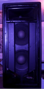
I would suggest a normal BR design. I had the same problem finding the right tops for my LAB subs. I really like horn designs but it's hard to make them go low enough to meet with modern subs. So we decided to try a BR approach. From all the horn building we done I almost forgot how nice a god BR design can play")
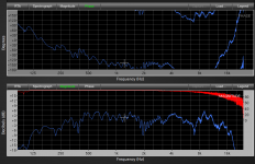
We decided on a 2x12" + 1,4" combo. Mid drivers are B&C 12NDL76 and high is 18sound ND1460A on a XT1464 horn.
The dip around 190Hz is from the height difference from the ground to the mic. Ground plane measurements show a flat response.
i like those cabinets SG3525. would 2 side by side cause problems?
Side by side placement of front loaded cabinets will cause off axis midrange comb filtering.i like those cabinets SG3525. would 2 side by side cause problems?
That does not stop people from using that arrangement.
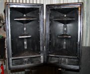
If the cabinet sidewall angle matches the HF horn's -6 dB point, and the HF horn dispersion matches the cone dispersion at the crossover point, and the cabinets are angled outward, the comb filtering is minimized.
Yes it took quite some time to get the comb filtering as minimized as possible. It's not perfect but far better than other similar cabs that i heard stacked together. In the middle where the cabinet walls are together you can hear some comb filtering going on but its very localized on that center point and you have to be listening for it or else you may not even hear it. When you move just a little bit off that center point the comb filtering is gone and the other cabinet takes over. So its far better than i hoped it would be.
The cabinet wall is angled at 20°.
The cabinet wall is angled at 20°.
Last edited:
would have if a wider angle was chosen for the nominally 60 degree dispersion horn, as the 18 Sound XT1464 horn has only about a 20 degree off axis -6 dB point at 10kHz, only 40 degree dispersion. The side by side pair would have about 80 degree dispersion at 10KHz.Yes it took quite some time to get the comb filtering as minimized as possible. It's not perfect but far better than other similar cabs that i heard stacked together. In the middle where the cabinet walls are together you can hear some comb filtering going on but its very localized on that center point and you have to be listening for it or else you may not even hear it. When you move just a little bit off that center point the comb filtering is gone and the other cabinet takes over. So its far better than i hoped it would be.
The cabinet wall is angled at 20°.
The problem with the pair of XT1464 horns placed side by side is the -6 dB point at 1kHz is 40 degree off axis, double the 10 kHz dispersion. The 20 degree overlap in the lower range of the horn will result in comb filtering, at certain points off axis in the midrange the dispersion will actually narrow.
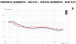
The “downright cute” (as jbell puts it) 2x6” with HF conical horn cabinet in post #30 by comparison maintains a uniform 45 degree off axis -6 dB coverage angle from 1kHz to 16 Khz.
The 90 degree pattern is more uniform than the pair of 18sound ND1460A on side by side XT1464 horns can be.
To maintain uniform dispersion in side by side placement requires the mid drivers as well as the HF drivers to use horns.
Attachments
Pretty darn close, with the usual caveat that Hornresp does not model upper breakup modes, and tends to exaggerate peaks and dips.
I'd show you the Smaart charts of my 8" drivers, but unfortunately at some point I deleted them.
Their response was very close to the VTC eL 210 shown below, around a 10-12 dB per octave drop below Fc.
The VTC chart cuts off before all the weird out of band upper junk happens, it is not pretty, and requires PEQ to get rid of it, it is audible even using a 24 dB per octave crossover.
That said, the acoustical HP the exit ports create eliminate a lot of harmonic distortion, I have run the 8" to Xmax and they still sound pretty darn clean, much better than BR cabinets at the same excursion.
At first glance, one would think the falling LF response would not allow a 100 Hz crossover, but when a number of cabinets are used the response becomes flat.
I actually have to cut the 8" response a bit down around the crossover point when using 67.5" ( the bottom 22.5" are 8" speakers only) of mid/top cabinets.
Using bass reflex ports could allow less modules to get flat down low, but at the expense of transient response. And since one ideally would want around one wavelength, 135 inches of line for a 100 Hz crossover, and I'm only half way there, the extra cones needed to get the LF are fine.
If I were to start from scratch (I have had the HF drivers since 1992, and the 8" for a decade or so) I'd be inclined to use four 6.5" and one (or two) 1" driver per cabinet, more height per $$ and more extended HF.
Art
Do you mind sharing the input parameters for Hornresp on your Paraline build? Thanks in advance.
I did not use Hornresp for the Paraline/offset horn build, the speaker port size was arrived at empirically after trying "too big" and "too small" and measuring which gave the best response.Do you mind sharing the input parameters for Hornresp on your Paraline build? Thanks in advance.
Art, how about 4xB&C 6NDL38 w/ 2xBMS 4550 per box?If I were to start from scratch (I have had the HF drivers since 1992, and the 8" for a decade or so) I'd be inclined to use four 6.5" and one (or two) 1" driver per cabinet, more height per $$ and more extended HF.
Art
- Status
- This old topic is closed. If you want to reopen this topic, contact a moderator using the "Report Post" button.
- Home
- Loudspeakers
- Subwoofers
- Tops to accommodate Xoc1's T18