You will understand that the many people will not be able to read your language.
Why not give the essence in a post?
/Hugo
never heard of the Google language tools?
go to
Language Tools
and fill out the URL address field with the originale URL:
Výkonový stupeň HQQF-55-503W-4-2
at next step you get
Google Translate
and now you can read in english - not perfect, but helpful
I have already helped someone with a Chinese text
You need to have IE6 or higher and install the Google Toolbar Google Toolbar
Or use Google Translate
never heard of the Google language tools?
Sure, but I prefer to read from the original author.
Maybe someone will be interested in how to create a 3D image of their products already in its earlier proposal.
Or how to animate images.
Or how to animate images.
An externally hosted image should be here but it was not working when we last tested it.
hi Federmann,
For inexperienced PCB designers like myself, I have found Eagle 3D a valuable tool to reduce or eliminate PCB errors before manufacture. For those with years of experience in PCB design, I guess generating a 3D models would be less useful. Nothing beats experience.
The only problem for most people with generating these 3D models is you need some programming skills to generate the 3D component models for custom components.
I haven't found any value in generating animated models though. Marketing maybe? Have you tried the method of defining your flight path on layer 230 in Eagle? (I couldn't see mention of it on your website)
regards
 I'm sweeping out this thread again. Federmann, I see that you have been copying posts and screenshots from here and putting them on your site in quantities well beyond any Fair Use. Please take them down immediately or be banned from this site.
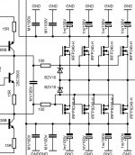
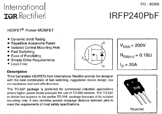
I am also very curious to understand how your novel output stage works. It uses only N-channel MOSFETs in both push-pull halves :
IRFP240 and IRFP9240 N and P
hi Greg Erskine,
I did everything described in three articles, there are two.
First How to 3D Eagle Basic installation of Eagle, Eagle 3D and Pov Ray. There are some forms package, they will come in handy when you do not know.
Second As 3D Eagle again Faultfinding
Regards
I did everything described in three articles, there are two.
First How to 3D Eagle Basic installation of Eagle, Eagle 3D and Pov Ray. There are some forms package, they will come in handy when you do not know.
Second As 3D Eagle again Faultfinding
Regards
Hi Federmann,
I tried using Google translation with your web site, and ended up with a spinning head as a result.
When you post, would you please refer to documents and information in English? Most of your work is somewhat lost on me due to the language barrier. I fear most of our membership may be in a similar position - unable to understand what you are doing.
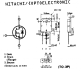
One part on your site refers to a transistor type. I guess it's a power mosfet made up from many smaller transistors inside. Can you elaborate please? My experience with current mosfets is that no source resistor = blown amplifier.
-Chris
I tried using Google translation with your web site, and ended up with a spinning head as a result.
When you post, would you please refer to documents and information in English? Most of your work is somewhat lost on me due to the language barrier. I fear most of our membership may be in a similar position - unable to understand what you are doing.
One part on your site refers to a transistor type. I guess it's a power mosfet made up from many smaller transistors inside. Can you elaborate please? My experience with current mosfets is that no source resistor = blown amplifier.
-Chris
hi Greg Erskine,
I did everything described in three articles, there are two.
First How to 3D Eagle Basic installation of Eagle, Eagle 3D and Pov Ray. There are some forms package, they will come in handy when you do not know.
Second As 3D Eagle again Faultfinding
Regards
Hi Federmann,
Thanks for the info. I have looked at your links and done my best to follow by looking at the pictures. I was wondering if you have used this method to generate you ini file. It creates a flythru rather than just rotating the 3D model.
en:eagle3d:documentation [www.matwei.de]
regards
Attachments
Besides the idea of putting N-ch devices in the lower part it's also quite interesting way how they are implemented as we know FETs have an intrinsic diode... *BOOM*
I could understand under time pressure if one didn't have a P-ch handy in the library to get the D and S right for P-ch one have to put the N-ch upside down to get the layout correct, but the designer with forty years of experience clearly told us he wanted to use N-ch makes me wonder if this all is a hoax, time is the truth teller....
I could understand under time pressure if one didn't have a P-ch handy in the library to get the D and S right for P-ch one have to put the N-ch upside down to get the layout correct, but the designer with forty years of experience clearly told us he wanted to use N-ch makes me wonder if this all is a hoax, time is the truth teller....
as we know FETs have an intrinsic diode... *BOOM*
Only JFETs
Only JFETs
Wrong.
Attachments
- Status
- Not open for further replies.
- Home
- Amplifiers
- Solid State
- Topology Federmann, HQQF-55 ...