Glad it's working - was it just being clipped by the raw CD level input then? I'm a bit confused as to what has changed.
As for CD quality, you may be surprised how shockingly bad the modern loudness enhanced CD really is.. the most important sonic attribute of a modern DAC is that it clips cleanly.
im not sure what has changed. i have reduced the output voltage of the cd player with the pot so that the preamp can amplify the signal without distorting. now the gain isnt so horribly high and a nice full rounded smooth tube sound results. i suppose i could just put the 250k pot right into the preamp chassis which now houses a 100k or i could put 200k resistors after the volume pot. im guessing.
interesting article about modern cds clipping, loss of dynamic range and poor mastering. strange that given all the ingenuity of today things seem to deterioriate on so many levels
are modern CDs devolving. i find it suprising that so many CDs have such poor quality sound. you would think sound engineers would have the gear to produce high quality reproductions consistently
Last edited:
So didn't the original pre-amp have an input pot at all then? That sounds unusual!
The CD is quite old now, back in those days 44.1kHz 16bit still sucked but was quite fast, now it just sucks. The suckiness is a terrible grating sound when you get quiet stuff and high frequency stuff. If you get both quiet and high frequency sound then CDs sound awful. As a result they need to be _loud_ to sound good, and ideally louder than your rivals, which results in removing dynamics and most of the realism of the sound. You can hear this in the latest young rock band's output - their loud bits are the same volume as the quiet passages - it's bizarre!
SACD was supposed to the the successor but the record industry killed it - it sounded so good that they didn't trust anyone who bought it, so they loaded it with DRM.
This is why LPs are still popular - they are obtainable (generally), loudness war free and so have interest of dynamics and timbre lacking from most CDs. After a while listening to digital the dynamics of an LP can still surprise me, and the treble is so effortless.
Which leaves todays DVD soundtracks as the best digital stuff you can buy. That's why film soundtracks often sound much better than CDs - it's because they are")
Maybe one day the record industry will connect decreasing audio quality and interest with decreasing interest in their products, but I'm not holding my breath.. so when hi-fi purists choose the latest speaker cables and mains conditioners they are generally unaware of the distorted mess that comes straight off their CDs
The CD is quite old now, back in those days 44.1kHz 16bit still sucked but was quite fast, now it just sucks. The suckiness is a terrible grating sound when you get quiet stuff and high frequency stuff. If you get both quiet and high frequency sound then CDs sound awful. As a result they need to be _loud_ to sound good, and ideally louder than your rivals, which results in removing dynamics and most of the realism of the sound. You can hear this in the latest young rock band's output - their loud bits are the same volume as the quiet passages - it's bizarre!
SACD was supposed to the the successor but the record industry killed it - it sounded so good that they didn't trust anyone who bought it, so they loaded it with DRM.
This is why LPs are still popular - they are obtainable (generally), loudness war free and so have interest of dynamics and timbre lacking from most CDs. After a while listening to digital the dynamics of an LP can still surprise me, and the treble is so effortless.
Which leaves todays DVD soundtracks as the best digital stuff you can buy. That's why film soundtracks often sound much better than CDs - it's because they are
Maybe one day the record industry will connect decreasing audio quality and interest with decreasing interest in their products, but I'm not holding my breath.. so when hi-fi purists choose the latest speaker cables and mains conditioners they are generally unaware of the distorted mess that comes straight off their CDs
You can hear this in the latest young rock band's output - their loud bits are the same volume as the quiet passages - it's bizarre!
So true unfortunately
For those of you who haven't experienced the "wonders" of heavy compression yet, try something along the lines of Hyper Enough by Superchunk (I believe you can find the complete music/video online), otherwise a fine tune that has been butchered by whoever edited that CD for them
So didn't the original pre-amp have an input pot at all then? That sounds unusual!
The CD is quite old now, back in those days 44.1kHz 16bit still sucked but was quite fast, now it just sucks. The suckiness is a terrible grating sound when you get quiet stuff and high frequency stuff. If you get both quiet and high frequency sound then CDs sound awful. As a result they need to be _loud_ to sound good, and ideally louder than your rivals, which results in removing dynamics and most of the realism of the sound. You can hear this in the latest young rock band's output - their loud bits are the same volume as the quiet passages - it's bizarre!
SACD was supposed to the the successor but the record industry killed it - it sounded so good that they didn't trust anyone who bought it, so they loaded it with DRM.
This is why LPs are still popular - they are obtainable (generally), loudness war free and so have interest of dynamics and timbre lacking from most CDs. After a while listening to digital the dynamics of an LP can still surprise me, and the treble is so effortless.
Which leaves todays DVD soundtracks as the best digital stuff you can buy. That's why film soundtracks often sound much better than CDs - it's because they are
Maybe one day the record industry will connect decreasing audio quality and interest with decreasing interest in their products, but I'm not holding my breath.. so when hi-fi purists choose the latest speaker cables and mains conditioners they are generally unaware of the distorted mess that comes straight off their CDs
yeah it did have the input pot but 100k ohms might be too low for my input from the cd player, from the specsthe cd player has output of 1.7 volts at 0 dB and impedance of 10k ohms or more. im not sure if these values are high or low or precisely how they affect matters.
So, if I digitize a record and store it as a 24bit wave file, then recorcd it to CD, does the CD retain the 24 bit encoding and thus have greater dynamic range than comercial CDs?
The CD retains the 24 bit encoding, whether it has greater DR than a commercial CD depends on a number of things.
It depends on the quality of your equipment and how good a job you do. Even if you do an excellent job you're unlikely to exceed the DR of a well-produced 16-bit CD.
It probably won't have any better DR than a well-produced CD of the same vintage as the original LP. An early Beatles or Stones (16-bit) CD will have as good DR as the original vinyl. That's why 16-bit was chosen for CDs at the time they were introduced.
Although many people insist that vinyl was superior to 16-bit CDs, this is largely a myth, and even if it were true, not many people have the turntables and cartridges capable of revealing said DR.
w
100k input load is fine for a preamp.
The theoretical dynamic range of a 16 bit CD is 96dB I.e. 6dB/bit, whereas a record is about 65dB IIRC. So a CD is about 30dB better, or about 5 bits.
So the quietest sound on a record will be 5bit audio on a CD, which each additional bit adding 6dB to the level.
Sadly 5bits is not hi-fi, not even close. The real problem with 15 bits is that the digital waveform resolution is linear, but sound is heard logarithmically - so on a CD all the fantastic resolution is at full volume, low volume is just a jagged low grade approximation. Listenable stuff on a record at an S/N of 24dB is therefore 8bit lo-fi on a CD, you just trade vinyl noise for CD inaccuracy.
24bits digital makes a big difference.
Many modern CDs don't seem to have a dynamic range,
Then there is the 44.1kHz - way way too low in my view. In theory you can have up to 22.05kHz without Nyquist aliasing - but that 22.05kHz will now be phase locked and level aliased to the bit-clock of the CD player, and the output filter will be expecting a 96dB/octave filter to just start cutting out aliasing an octave up. Oversampling helps enormously - but then just sampling faster in the first place does too - like at 96kHz instead. Oversampling is basically making the extra points up by simulating a low pass filter.
Try a DVD film with 96kHz and/or 24bit audio one day and be amazed at the volume you can sustain - with a CD your ears tell you to turn it down at a pretty early stage - generally not so with vinyl and DVD.
BTW 'How loud is comfortable' is my primary test of hi-fi as your ears tell you the 'pleasantness' of the sound more than the level
A typical modern rock CD:
Not very dynamic
Most early CDs were not clipped like that (that one is both compressed and clipped) but instead mastered to sound awful at any level as people got to grips with how to master a CD well.
Taking the best of vinyl and CD you end up with 24bit/96kHz. Big files, difficult to download but easy to buy on DVD - but the record company will not sell them.
The CD retains the 24 bit encoding, whether it has greater DR than a commercial CD depends on a number of things.
It depends on the quality of your equipment and how good a job you do. Even if you do an excellent job you're unlikely to exceed the DR of a well-produced 16-bit CD.
It probably won't have any better DR than a well-produced CD of the same vintage as the original LP. An early Beatles or Stones (16-bit) CD will have as good DR as the original vinyl. That's why 16-bit was chosen for CDs at the time they were introduced.
Although many people insist that vinyl was superior to 16-bit CDs, this is largely a myth, and even if it were true, not many people have the turntables and cartridges capable of revealing said DR.
w
The theoretical dynamic range of a 16 bit CD is 96dB I.e. 6dB/bit, whereas a record is about 65dB IIRC. So a CD is about 30dB better, or about 5 bits.
So the quietest sound on a record will be 5bit audio on a CD, which each additional bit adding 6dB to the level.
Sadly 5bits is not hi-fi, not even close. The real problem with 15 bits is that the digital waveform resolution is linear, but sound is heard logarithmically - so on a CD all the fantastic resolution is at full volume, low volume is just a jagged low grade approximation. Listenable stuff on a record at an S/N of 24dB is therefore 8bit lo-fi on a CD, you just trade vinyl noise for CD inaccuracy.
24bits digital makes a big difference.
Many modern CDs don't seem to have a dynamic range,
Then there is the 44.1kHz - way way too low in my view. In theory you can have up to 22.05kHz without Nyquist aliasing - but that 22.05kHz will now be phase locked and level aliased to the bit-clock of the CD player, and the output filter will be expecting a 96dB/octave filter to just start cutting out aliasing an octave up. Oversampling helps enormously - but then just sampling faster in the first place does too - like at 96kHz instead. Oversampling is basically making the extra points up by simulating a low pass filter.
Try a DVD film with 96kHz and/or 24bit audio one day and be amazed at the volume you can sustain - with a CD your ears tell you to turn it down at a pretty early stage - generally not so with vinyl and DVD.
BTW 'How loud is comfortable' is my primary test of hi-fi as your ears tell you the 'pleasantness' of the sound more than the level
A typical modern rock CD:
An externally hosted image should be here but it was not working when we last tested it.
Not very dynamic
Most early CDs were not clipped like that (that one is both compressed and clipped) but instead mastered to sound awful at any level as people got to grips with how to master a CD well.
Taking the best of vinyl and CD you end up with 24bit/96kHz. Big files, difficult to download but easy to buy on DVD - but the record company will not sell them.
So, if I digitize a record and store it as a 24bit wave file, then recorcd it to CD, does the CD retain the 24 bit encoding and thus have greater dynamic range than comercial CDs?
http://en.wikipedia.org/wiki/Red_Book_(audio_Compact_Disc_standard)
You cannot stuff 24 bits worth of information into 16 bits of room (at least not for any set of input data). Some data has to be truncated, now whether this data contained any useful information or just noise is a different matter alltogether. Each additional bit contributes 6 db to maximum dynamic range so - in theory - audio CD could represent 16*6 = 96 dB dynamic range under ideal circumstances (if music was normalized to full scale).
You cannot stuff 24 bits worth of information into 16 bits of room
Yes, but you can store a 24-bit datafile on a CD. Mono, stereo, 44k1, 196k, big-endian, little-endian, it's all just data. If you have the wit you can write the code to manipulate it, if you can't get it off-the-shelf. If you haven't you can always ask me, but I regard anything above 16-bit 48k PCM for domestic playback as superfluous, so be warned.
w
I did have a slightly more colourful phrase about mammary glands on male bovines in there, but in deference to the kindness shown me by at least one of the moderators, I took it out...
Yes, but you can store a 24-bit datafile on a CD. Mono, stereo, 44k1, 196k, big-endian, little-endian, it's all just data.
Indeed, but this is no longer a Red book compliant audio CD then and most audio CD players will now be able to reproduce the nice 24 b/s data from it.
Indeed, but this is no longer a Red book compliant audio CD
Correct.
w
Indeed, but this is no longer a Red book compliant audio CD then and most audio CD players will now be able to reproduce the nice 24 b/s data from it.
Ugh, how I absolutely loathe the magically dissapearing EDIT BUTTON

Above should say 'not' rather than 'now' which might not be evident despite the context.
...most audio CD players will [not] be able to reproduce the nice 24 b/s data from it.
...no, but if the data was created on a PC in e.g. Cubase using a 24-bit soundcard, then the data could be reloaded into Cubase and replayed through the 24-bit soundcard with whatever dynamic range and bandwidth had been achieved at the time of recording (given that no soundcard that I have seen thus far actually achieves 24 bits of dynamic range). I never intended to suggest anything more...
w
...no, but if the data was created on a PC in e.g. Cubase using a 24-bit soundcard, then the data could be reloaded into Cubase and replayed through the 24-bit soundcard with whatever dynamic range and bandwidth had been achieved at the time of recording (given that no soundcard that I have seen thus far actually achieves 24 bits of dynamic range). I never intended to suggest anything more...
What's the point? AIF or WAV files that Cubase stores may be recorded to any file system that can be mounted on current OS.
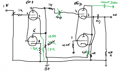
Here are some simple things to help this circuit out.the gain is way too high, i can only turn the volume up about 30% and then it starts to distort. it doesnt use feed back it is a dual paralleled single ended triode with a cathode follower.
here is the schematic of one channel, the pot is 100k
Put a 100uf 350 cap to ground off of the plates of the 2nd stage. I would consider eliminating the 47K plate resistor entirely.
On the first two tubes, which are in parallel, install a 50 ohm resistor in series with each cathode. This will help the tubes act more as if they are in parallel.
You do not need the coupling cap between the 2 stages if you get rid of the 47K plate resistor in the 2nd stage. Again a 50 ohm resistance in series with each cathode of the 2nd stage will help those tubes work better together.
If it were me, I would replace the 220K plate resistor of the first stage with 100K. That will reduce the gain somewhat and give you better bandwidth.
Have fun- don't zap yourself.
Here are some simple things to help this circuit out.
Put a 100uf 350 cap to ground off of the plates of the 2nd stage. I would consider eliminating the 47K plate resistor entirely.
On the first two tubes, which are in parallel, install a 50 ohm resistor in series with each cathode. This will help the tubes act more as if they are in parallel.
You do not need the coupling cap between the 2 stages if you get rid of the 47K plate resistor in the 2nd stage. Again a 50 ohm resistance in series with each cathode of the 2nd stage will help those tubes work better together.
If it were me, I would replace the 220K plate resistor of the first stage with 100K. That will reduce the gain somewhat and give you better bandwidth.
Have fun- don't zap yourself.
thanks a lot for this advice. do you mean like the attachment here?
i followed an alternative schematic for the cathodes in the first stage using the 1.5k values, this cleared up quite a bit of hum i was getting. im still having a hum problem but i think that might be solved by reducing the filament voltage from over 7v ac down to 6v or so.
you mentioned using 50ohm? im not clear on this part.
dont need the coupling cap? dont i want to isolate the dc voltage of the first stage from the second and allow the signal to pass? im new to this im just testing my understanding which is very limited.
get rid of the of the 47k in the second stage. did i cross out the right one?
replacing the 220k with a 100k means that there will be less voltage across that resistor and more across the tube. is this right? wont this increase the gain? i dont know.
the 100uF cap to ground off of the plates in the second stage, what will this do ground out some high frequencies?
thanks a lot for your suggestions and help
Attachments
im still having a hum problem but i think that might be solved by reducing the filament voltage from over 7v ac down to 6v or so.
you mentioned using 50ohm? im not clear on this part.
dont need the coupling cap? dont i want to isolate the dc voltage of the first stage from the second and allow the signal to pass? im new to this im just testing my understanding which is very limited.
get rid of the of the 47k in the second stage. did i cross out the right one?
replacing the 220k with a 100k means that there will be less voltage across that resistor and more across the tube. is this right? wont this increase the gain? i dont know.
the 100uF cap to ground off of the plates in the second stage, what will this do ground out some high frequencies?
thanks a lot for your suggestions and help
The cathodes of the first stage tubes will still be tied together. But the idea is to put a small resistance (50 ohms) in series with *each cathode* and have them join together at the 1.5K resistor to ground.
The 47K gets jumpered with a bit of wire, same for the coupling cap. The 100uf cap will ground *all* frequencies and insure that the plate is held at a constant point so that the tube will act as a cathode follower.
I would do something to get the filament voltage down as you will bake your tubes otherwise. That may help with the hum but IMO you need to lay the components out more carefully- less 'flying wires', keep your leads short, that sort of thing. Keeping the finished circuit looking neat is important as you will find yourself looking for the optimal layout to do so; if your layout is sloppy you can pick up hum, induce oscillation (which can result in hum) and reduce bandwidth.
BTW I would put a resistance of between 150 to 1000 ohms in series with each grid of each tube, which is known as a grid-stop resistor. There is one shown in the schematic tied to pin 1 of the first tube. There should be two there- one for each grid, and two more for the 2nd stage grids. That 1K resistor off the plate of the 1st stage should really be on the gird of the 2nd stage after the cap (which we are going to eliminate). Its things like this in the schematic that I think convinced others that the schematic was not right or else was poorly designed. Normally the resistor body is fairly close to the tube. This will reduce RF issues and often thus reduces noise. FWIW, no tube circuit can be expected to be competent without grid stops!
Last edited:
The cathodes of the first stage tubes will still be tied together. But the idea is to put a small resistance (50 ohms) in series with *each cathode* and have them join together at the 1.5K resistor to ground.
The 47K gets jumpered with a bit of wire, same for the coupling cap. The 100uf cap will ground *all* frequencies and insure that the plate is held at a constant point so that the tube will act as a cathode follower.
I would do something to get the filament voltage down as you will bake your tubes otherwise. That may help with the hum but IMO you need to lay the components out more carefully- less 'flying wires', keep your leads short, that sort of thing. Keeping the finished circuit looking neat is important as you will find yourself looking for the optimal layout to do so; if your layout is sloppy you can pick up hum, induce oscillation (which can result in hum) and reduce bandwidth.
BTW I would put a resistance of between 150 to 1000 ohms in series with each grid of each tube, which is known as a grid-stop resistor. There is one shown in the schematic tied to pin 1 of the first tube. There should be two there- one for each grid, and two more for the 2nd stage grids. That 1K resistor off the plate of the 1st stage should really be on the gird of the 2nd stage after the cap (which we are going to eliminate). Its things like this in the schematic that I think convinced others that the schematic was not right or else was poorly designed. Normally the resistor body is fairly close to the tube. This will reduce RF issues and often thus reduces noise. FWIW, no tube circuit can be expected to be competent without grid stops!
so much to learn! thanks for the input. i dont feel competent enough at all to implement these changes from the verbal description right now.
i am writing down these notes in a notebook so i can digest them as my understanding improves.
ill try to draw a schematic and maybe you can check it to see if i have it right
you said that there is a grid stopper resistor tied to pin 1 of the first tube, did you mean pin 2? pin one is the plate
thanks a lot
Last edited:
i found this diagram.
The grid stopper resistor RGS blocks radio frequencies while allowing audio signals to pass. This keeps the amplifier from becoming a radio receiver and prevents the stage from breaking into parasitic oscillation.
i have some 330ohm resistors. i guess they would work right?
The grid stopper resistor RGS blocks radio frequencies while allowing audio signals to pass. This keeps the amplifier from becoming a radio receiver and prevents the stage from breaking into parasitic oscillation.
i have some 330ohm resistors. i guess they would work right?
Attachments
Last edited:
so much to learn! thanks for the input. i dont feel competent enough at all to implement these changes from the verbal description right now.
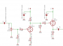
Would schematic help ? I drew one just for you. Unlike what you've got there it's actually suited to 6N1P tubes and shouldn't be just a distortion box. If you intend to keep the silly double tube with shared load resistor arrangement, halve the values of R4 and R7 (each tube sees same load so when paralleled, the combined load is 1/2 the load of a single tube).
This assumes supply voltage V+ of 200-300V.
I just noticed a typo: "at keast" should of course be "at least"
As for replacing R8 with green LED (which should improve gain and probably sound better): make sure you buy the cheapest example of low luminance low current matte dome kind that is avaliable to you (the more expensive high luminance bright green types have considerably higher Vf and will again bias the first stage waaay into non-linear region). LED must light up when circuit is turned on - if it doesn't, you've got its polarity wrong and you must reverse it.
Attachments
- Status
- This old topic is closed. If you want to reopen this topic, contact a moderator using the "Report Post" button.
- Home
- Amplifiers
- Tubes / Valves
- too much gain