i use a wire ampacity of 500 circular mils per ampere but it can vary more or less..
.
Yes I can confirm this is what I also use for a baseline XFMR calc. 30-40 degree rise> use more copper for poor cooling in fully enclosed or still air, less copper for fan cooled.
......................3. i use a wire ampacity of 500 circular mils per ampere but it can vary more or less.................
Yes I can confirm this is what I also use for a baseline XFMR calc....................
Does that come out at 0.253sqmm per Ampere?1 circular mil = 0.0005067 mm².............
i.e. 4A/sqmm?
I see toroids and EIs using between 3A/sqmm and 6A/sqmm
I have liitle experience of C & R core types.
Circular Mils to Square Millimeters | Kyle's Converter
anywhere from 300 to 700 circular mils per ampere can be used,
i have seen a wire table suggest 1500 cm per ampere...
depends on the traffo designer what he wants to achieve,
no hard and fast rules but a lot of common sense, the fun
is in knowing when and why to use those data...
and there are no formulas for those...
Yes I can confirm this is what I also use for a baseline XFMR calc. 30-40 degree rise> use more copper for poor cooling in fully enclosed or still air, less copper for fan cooled.
in my years of building traffos, i found that 500CM per ampere works out alright due to the limited winding space....
but where winding space is relatively larger, then bigger size wires can be used,
this is just plain common sense....

but where winding space is relatively larger, then bigger size wires can be used,
this is just plain common sense....
A old seasoned guru told me that rule of thumb and Ive committed that to permanent memory long ago , so when I saw your post, the musical bells started ringing in my ears.
Interestingly I found it works well in SMPS too. baseline design of course. At higher frequencies we have skin effect so...adjust for larger round wires. High current secondary's with copper foil sheets the cross section is converted to cir mils. The magnet wire vendors gave us these nifty cardboard pocket table/ calculator cards.
Last edited:
my other rule of thumb, you learn by doing, mostly doing...
The problem is that it might discourage othervise perfect winders who only lacks the recipie, a step down list of "how to" from a set of prerequisites to do the specified calculations. I do not see the way into this viable trough trial and error - if one like me do not have time which is quite normal in todays world. The most of us have this as an hobby - we have more demanding duties as feeding our families and pay the rents. So the recipie is still missing... Yes, I have seen your photo of your workbook - I've printed it out and understand most of it for that project. My view is as I understand bits of it it can't be rocket sience for you Tony or someone else to once and for all create a recipie with input and output values which gives the different prereqs for the given inputs.
Your workbook with comments would be appreciated where it would be a living document with more comments when questions arise. Would it be undoable or not of interest?
Regards
Your workbook with comments would be appreciated where it would be a living document with more comments when questions arise. Would it be undoable or not of interest?
if you can decipher it....
, even myself sometimes gets confused....but since retirement fro overseas working in 2011, i have kept lots of notes,
in several notebooks.....
i also have spreadsheets on my desktop that i look at at times...
as for a recipe, YvesM. has one, do seek out his posts in our forum and in this website..

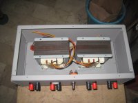
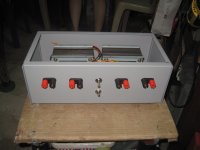
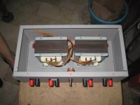
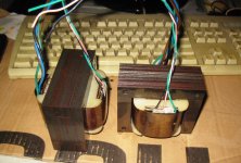
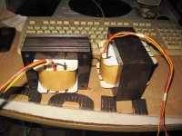
@Turbon, nice bobbins. did you make them yourself? sectioned bobbins make winding faster and insulations are easy....
Thanks Tony.
Yes, homebrewed. The coreparts and the outer walls are 1mm epoxyboard. The intersections are of 0,5mm. The output shall be 2*360V 400mA. I'm trying to figure out what would be the most useful 5 taps to make.
Regards
Thanks Tony.
Yes, homebrewed. The coreparts and the outer walls are 1mm epoxyboard. The intersections are of 0,5mm. The output shall be 2*360V 400mA. I'm trying to figure out what would be the most useful 5 taps to make.
Regards
Well, the question about taps has already been answered - for experimentation - use a variable mains transformer...
Regards
Right, minor adjustments needed. Then it is time to epoxy it and maximize the stack. I have been able to stack to my goal of 81mm but I can probably squeeze in at least 1mm more. I will keep the intersections movable as I haven't decided the maximum current yet. I planned for 400mA at 720V divided on 2HT windings but I think that it could be made 0,5A instead. Not sure yet...
https://m.imgur.com/JlqIrYv
Sorry, I do not know how to upload inline pics... I can only use external links for a reason I presume.
Regards
https://m.imgur.com/JlqIrYv
Sorry, I do not know how to upload inline pics... I can only use external links for a reason I presume.
Regards
Last edited:
- Home
- Amplifiers
- Power Supplies
- Tony's latest traffo DIY build