10 OP tells me nothing.
What does 10 OP tell you?
Had you said a 5pair output stage using 150W devices then we can estimate the maximum power as ~ 10 * 150 / 5 ~ 300W into your speaker load.
Stereo would be 300W+300W. That typically requires 600VA to 1200VA to perform well.
Do you see that 10 OP means nothing?
What does 10 OP tell you?
Had you said a 5pair output stage using 150W devices then we can estimate the maximum power as ~ 10 * 150 / 5 ~ 300W into your speaker load.
Stereo would be 300W+300W. That typically requires 600VA to 1200VA to perform well.
Do you see that 10 OP means nothing?
Last edited:
AndrewT if it will yeild me to higher VA I will combine the two trafo as it has the same Size EI core.
You might have a problem with that because the thick core uses so much wire. Also the window or hole on the core only allows so much wire. so the window size places a limit on the total number (primary plus all secondaries) or turns. You may not be able to fit all those turns unless you use smaller diameter wire. Then you have problems with DC resistance and current handling.
The best plan is to say to yourself "OK I have this core, what is the best transformer I can build with it?" and then accept whatever VA rating you get.
In general you want to stack lamiates until the core is "square" and then look at the Window size to see how many turns you can do.
One more thing: Very important especially on a home made PT. You want a SPLIT bobbin so that the primary can't possible come in contact with the secondary and short. Don't depend on paper insulation. This is a safety issue. This will use up some of your window area. But it is worth is because you only get to make a mistake with lethal voltages once.
The best plan is to say to yourself "OK I have this core, what is the best transformer I can build with it?" and then accept whatever VA rating you get.
Hi Chris,
This is exactly what I trying to do, if I can get a result of 1000VA combining the EI cores from two trafo..I can see a possibility with it. I know how to follow/implements the safety in terms of winding it but still I need the following:
- Primary turns
- Secondary turns
- Primary wire gauge
- Secondary wire gauge
Junie
Hi Chris,
This is exactly what I trying to do, if I can get a result of 1000VA combining the EI cores from two trafo..I can see a possibility with it. I know how to follow/implements the safety in terms of winding it but still I need the following:
Cheers,
- Primary turns
- Secondary turns
- Primary wire gauge
- Secondary wire gauge
Junie
No one can tell you that answer straight off. but here is how to figure it out...
1) You know the turns RATIOS so write the turns counts as a relaive expression. for example
Primmary turns = 1X
Secondary turns = .45X
This will give you a secondary voltage or 0.45 times the ACmains voltage. So adjust the ".45" number to what ever you like
2) figure out the ratio of the wire gauges. Current carrying ability depends on the cross section area of the wire. Current will be the inverse of voltage. Area is of course pi * r^2. Call this area Ap and As
3) The total number of wires going through the window is 1x + .45x. The total square area of all the wires is 1XAp + .45XAs
4) set the above equal to the available window area (allow for packing density) and solve for X. X is the number of turns that will fit.
5) If you don't like X because of either of the following reasons, adjust the wire diameter and try again
5a) You might saturate the core if X is to large for the core area or
5b) reactance at 60Hz might be to low.
Check for both
6) repeat the above as many times as required.
7) using the above method means that the answer to "how many turns?" is "as many as will fit on your core. If there is space left in the window it means youe wire size is to small and you could have used bigger wire. so ALWAYS fill all of the space. You may have to do the calculations many times.
one thing that will help is to wind some wire around a platic pipe use insolation over each layer and measure yourself and see howm many turns per square cm you can do. This number depends on not only the wire but your skill as a building.
So I doubt some one will tell you an exact answer
Sir Tony it's 0.5mm, I'm planning to use the trafo for Leach amp with 10 O/P tranny. Thanks.
have you built a traffo before?
the "ideal traffo" will have a square cross section, but it doesn't mean you can not use your existing core materials.
are you going to do sine wave testing? or just play music?
AndrewT if it will yeild me to higher VA I will combine the two trafo as it has the same Size EI core.
since you have those materials on hand already you might as well use them....

pm me for more details...
So I doubt some one will tell you an exact answer
indeed, ten designers will return you with ten different solutions....
have you built a traffo before?
the "ideal traffo" will have a square cross section, but it doesn't mean you can not use your existing core materials.
are you going to do sine wave testing? or just play music?
Square is ideal because the amount of wire required for a given inductance is minimized. Of course you can use a shape that is more rectangular.
What this person needs is the best PT he can get from this core. I tried to give him a step by step way to figure this out or at least so that he can ask better and more specific questions.
He is unlikely to get a design all neatly worked out but now he can ask questions like "what is a reasonable assumption for packing density?" or "what is the ampancy of various diameter wires when used inside a PT as opposed to in free air?" He will get good answers to questions like those.
best is a broad word......
it starts with the winding window, it is constant by physical dimensions, a stack of 1inch will have the same window as a stack of say 10 inches...
only the core area and therefore power handling changes...
having the winding window area, allow 80% of that for copper...
of that 80%, 50% is for the primary winding and the other 50% for the secondary winding...
once you know how many turns is required at primary you can then look at possible wire sizes that will fit into that window, i use 500cm per ampere current density...
knowing the winding window area, you can then consult the wire table to find out how many turns you can fit into that space.....
knowing the wire size you are going to use, you will know how many amperes the wire can safely carry and therefore you can estimate primary power handling.....most of the time this will be lower than the core power handling estimated before....you can use the biggest wire that will fit in your window...
you will find that you will have to compute and recompute, it is a repetitive process....
designing and building traffos takes a lot of compromises, and these where newbies will have a hard time......do you want tight regulation so that you operate at higher flux density, and end up with a hot traffo or you want a cool running traffo but in turn use more copper? the answer to that depends on your priorities....
been doing this for the last 30 years or so and sometimes you just know.....nothing secret just hard work...
Sir Tony,
I already dismantle one of the trafo i have, the bobbin size is 51mm x 42mm. I sent you PM for my requirements. I found this site interesting Practical Transformer Winding, what do you think of it?
I already dismantle one of the trafo i have, the bobbin size is 51mm x 42mm. I sent you PM for my requirements. I found this site interesting Practical Transformer Winding, what do you think of it?
Attachments
when winding traffos with wire sizes as big as these, i do it manually with the help of another....
hi tony,
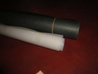
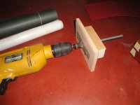
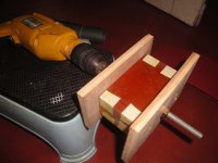
i made the bobbin with pcb board.
the problem is i cant wind the wire with straight.
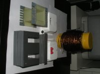
the wire is very thick and i burn the wire with lighter, the enamel is not removing. i think this is good quality wire.
any method for winding this wires?
i will post images when my camera return from my friend.
...
the problem is i cant wind the wire with straight. the wire is very thick....
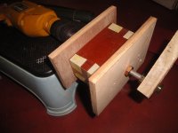
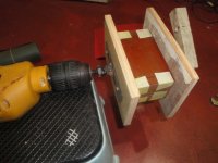
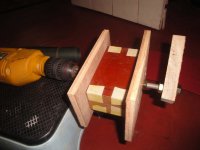
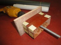
I think with thick wire some people use wood blocks and clamps to compress the winding so that it will be straight and fit in the core. You only have to compress one side, let the other get larger.
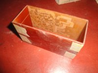
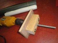
i tried with this jig.
the bobbin size is 1.75 inch centerleg, core stack 4.5 inch. i made with pcb board.
the bobbin size is 1.75 inch centerleg, core stack 4.5 inch. i made with pcb board.
Attachments
-
 DSC04180 copy.jpg175.6 KB · Views: 150
 -
 DSC04179 copy.jpg106.7 KB · Views: 149
 -
 DSC04178 copy.jpg105 KB · Views: 152
 -
 DSC04174 copy.jpg61.5 KB · Views: 147
 -
 DSC04173 copy.jpg99.7 KB · Views: 305
 -
 DSC04172 copy.jpg98.4 KB · Views: 316
 -
 DSC04171 copy.jpg105.2 KB · Views: 319
 -
 DSC04169 copy.jpg106.6 KB · Views: 367
 -
 DSC04177 copy.jpg107.3 KB · Views: 162
Last edited:
- Home
- Amplifiers
- Power Supplies
- Tony's latest traffo DIY build